Electric power storage system

a technology of electric power storage and battery, which is applied in the direction of secondary cell servicing/maintenance, battery/fuel cell control arrangement, etc., can solve the problems of reducing the input and output of the battery after external charging, the voltage of the battery may exceed the upper limit voltage, and the battery may deteriorate, so as to reduce the deterioration of the battery, the effect of reducing the temperature of the battery and reducing the charging power supplied to the battery

Active Publication Date: 2017-05-04
TOYOTA JIDOSHA KK
View PDF0 Cites 19 Cited by
  • Summary
  • Abstract
  • Description
  • Claims
  • Application Information

AI Technical Summary

Benefits of technology

[0013]The charging power supplied to the battery is reduced as the state of charge of the battery is higher, such that the charging power supplied to the battery can be suitably controlled, even if the power supply to the battery heater is stopped while charging and heating of the battery are carried out, and the power is diverted and added to the charging power. Therefore, the voltage of the battery is less likely or unlikely to exceed the upper-limit voltage under the first charge control, while the chance of raising the temperature of the battery is assured. Thus, deterioration of the battery can be reduced.
[0014]In the electric power storage system as described above, the charge control may include first charge control and second charge control. The first charge control is performed by the controller when the state of charge of the battery is equal to or smaller than the predetermined value, and including a plurality of control zones. The control zones are defined based on a magnitude of the state of charge of the battery. The second charge control is performed by the controller when the state of charge of the battery is larger than the predetermined value. The controller may be configured to perform the charge control while performing the temperature regulation control, such that charging power supplied to the battery is reduced, and the power supplied to the battery heater is reduced, as the state of charge of the battery in one of the control zones in which the first charge control is currently performed is higher.
[0015]As the battery is charged, the state of charge of the battery increases, and the voltage of the battery increases toward the upper-limit voltage. Therefore, the first charge control may be divided into a plurality of control zones depending on the magnitude of the state of charge of the battery, and the power supplied to the battery heater may be reduced, and the charging power supplied to the battery may be reduced, as the SOC of the battery in the current control zone is higher. With this arrangement, even if supply of the power to the battery heater is stopped while the battery is being charged and heated, the amount of power diverted and added to the charging power can be reduced. Also, even if the power supplied to the battery heater is diverted and added to the charging power, the charging power supplied to the battery can be controlled to a relatively low level. Accordingly, in the first charge control, the voltage of the battery is less likely or unlikely to exceed the upper-limit voltage while the chance of raising the temperature of the battery is assured. Consequently, degradation of the battery can be reduced.

Problems solved by technology

This is because, when the temperature of the battery (battery temperature) is reduced, the internal resistance increases, and the charging efficiency deteriorates, resulting in reduction of the input and output of the battery after external charging.
If the SOC of the battery is at a high level at this time, the voltage of the battery may exceed the upper-limit voltage, due to the rapid increase of the charging power.
If the voltage of the battery exceeds the upper-limit voltage, the battery may deteriorate.

Method used


Image

  • Electric power storage system
  • Electric power storage system
  • Electric power storage system

Examples


Embodiment Construction

[0032]Embodiments are described below.

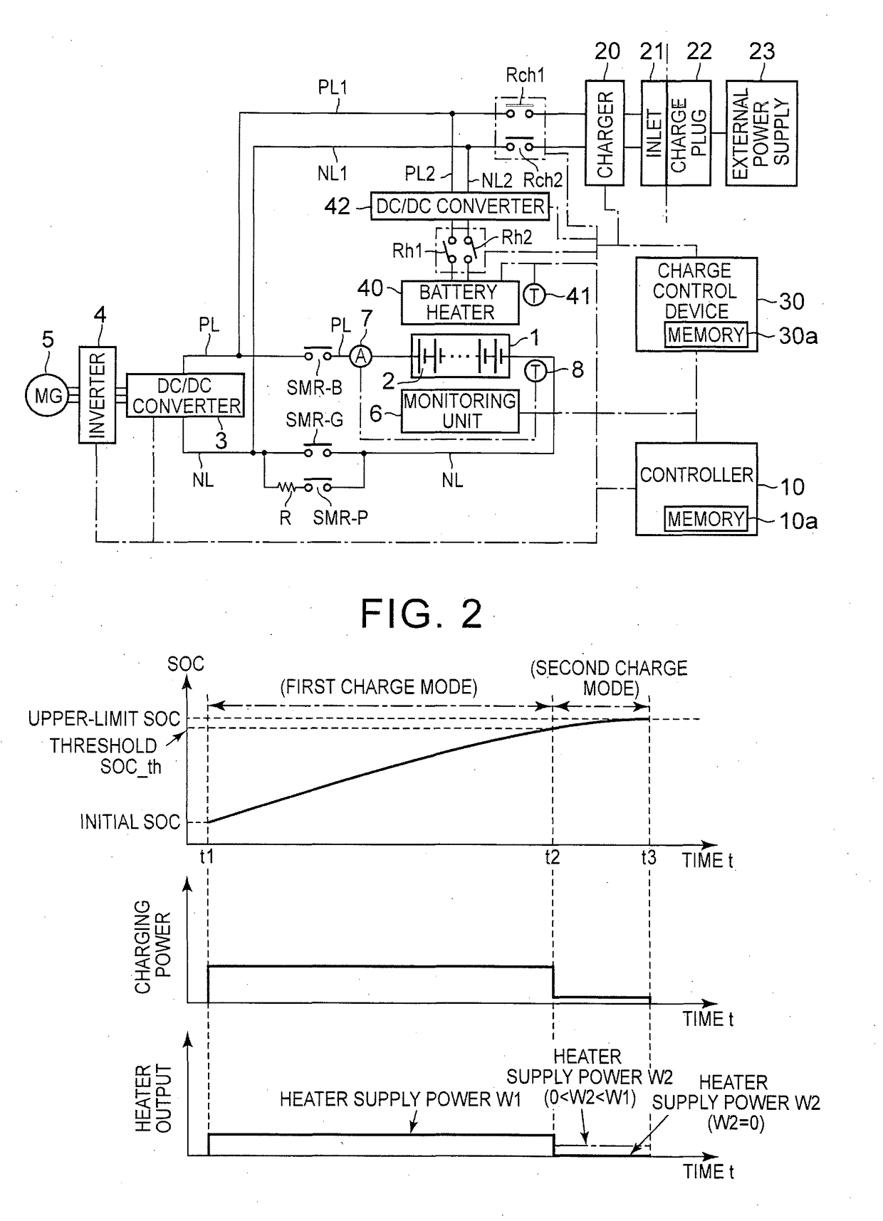
[0033]FIG. 1 through FIG. 7 show embodiments. FIG. 1 is a block diagram showing the configuration of a battery system installed on a vehicle. The battery system may be installed on a vehicle, such as a plug-in hybrid vehicle having a function of charging a battery with power from an external power supply, or an electric vehicle.

[0034]The battery system of some embodiments includes a charge / discharge system and an external charge system. In the charge / discharge system, DC power is supplied from a battery 1 to a motor-generator (MG) 5 via an inverter 4, and the battery 1 is charged with regenerative energy during braking of the vehicle. In the external charge system, a temperature regulator is provided for the battery 1, and the battery 1 is charged with electric power from an external power supply 23.

[0035]As shown in FIG. 1, the battery 1 is a battery assembly having a plurality of unit cells 2 electrically connected in series. As each of the un...


PUM

PropertyMeasurementUnit
electric poweraaaaaaaaaa
temperatureaaaaaaaaaa
poweraaaaaaaaaa

Abstract

An electric power storage system for a vehicle includes a temperature sensor configured to detect a temperature of a battery, a battery heater, a charger connectable with an external power supply and configured to deliver external power to the battery and the battery heater, and a controller. In the system, a first electric power is supplied to the battery heater when the state of charge of the battery is larger than a predetermined value and the temperature of the battery is equal to or lower than the predetermined temperature, and a second electric power is supplied to the battery heater when the state of charge of the battery is equal to or smaller than the predetermined value and the temperature of the battery is equal to or lower than the predetermined temperature. The first electric power is smaller than the second electric power.

Description

CROSS-REFERENCE TO RELATED APPLICATIONS[0001]This application is a National Stage of International Application No. PCT / M2015 / 000756 filed on May 26, 2015, which claims priority to Japanese Patent Application No. 2014-110369, filed May 28, 2014, the entire contents of which are hereby incorporated by reference.BACKGROUND[0002]1. Field[0003]The disclosure relates to an electric power storage system for a vehicle, which includes a battery that supplies electric power to a motor for moving the vehicle and is chargeable with electric power supplied from an external power supply.[0004]2. Description of Related Art[0005]In a plug-in hybrid vehicle or an electric vehicle, a battery that supplies electric power to a motor for moving the vehicle can be charged (externally charged) with electric power supplied from an external power supply. In a control system as described in Japanese Patent Application Publication No. 2012-191782 (JP 2012-191782 A), a part of external power is delivered to a ...

Claims


Application Information

Patent Timeline
Patent Type & Authority Applications(United States)
IPC IPC(8): B60L11/18H01M10/615H02J7/04
CPCB60L11/1875B60L11/1811H01M2220/20H01M10/615H02J7/04H02J7/0091H02J7/087H01M10/625H01M10/6571H01M10/425H01M10/443H01M10/486B60L7/16Y02T10/7072Y02T90/14B60L1/02B60L2240/545B60L53/14B60W10/26B60W2510/244B60W2510/246B60L58/27B60L58/15H02J7/007194Y02T10/70Y02E60/10B60K6/48
Inventor MURATA, TAKASHIMASUDA, TOMOKAZU
Owner TOYOTA JIDOSHA KK
Why Eureka
Try Eureka