Clock delay compensation device and clock delay compensation synchronization method

A post-compensation and clock technology, which is applied in the field of clock synchronization, can solve the problems of large error between the calibration clock and the standard clock, difficult measurement and estimation of time stamp error signal processing time, time stamp error, etc., and achieve high clock synchronization accuracy.

Active Publication Date: 2011-03-16
烟台持久钟表集团有限公司
View PDF8 Cites 1 Cited by
  • Summary
  • Abstract
  • Description
  • Claims
  • Application Information

AI Technical Summary

Problems solved by technology

In the second step, after the transmission delay d, the calibrated clock receives the above-mentioned clock synchronization signal, and records the received time stamp, wherein the actual time when the calibrated clock receives the clock synchronization signal is T 1 , but the time of record reception is T 2 , so a time stamp error t will be generated in this step
The fourth step is to adjust the synchronization time T of the calibrated clock 3 = T 0 +d; Among them, the transmission delay d is known, but the time stamp error t and the signal processing time tˊ are difficult to measure and estimate, so the synchronization time accuracy obtained by this clock synchronization method is poor, see Figure 5
In this way, the error between the calibrated clock and the standard clock is relatively large, and it is not suitable for nuclear power, high-speed rail, stations, airports and other places that require high clock accuracy.

Method used


Image

  • Clock delay compensation device and clock delay compensation synchronization method
  • Clock delay compensation device and clock delay compensation synchronization method
  • Clock delay compensation device and clock delay compensation synchronization method

Examples


Embodiment Construction

[0030] The principles and features of the present invention are described below in conjunction with the accompanying drawings, and the examples given are only used to explain the present invention, and are not intended to limit the scope of the present invention.

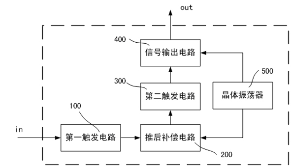
[0031] As an aspect of the present invention, such as figure 1 As shown, the clock delay compensation device includes a first trigger circuit 100 , a delay compensation circuit 200 , a second trigger circuit 300 , a crystal oscillator 400 , and a time output circuit 500 . The crystal oscillator 400 is connected to the time output circuit 500 and the delay compensation circuit 200 respectively, and the delay compensation circuit 200 is also connected to the first trigger circuit 100 and the second trigger circuit 300 respectively, and the second trigger circuit 300 is also connected to the time output circuit 500 connected. Among them, the crystal oscillator 400 is used to provide a stable clock frequency to the ti...


PUM


Abstract

The invention relates to a clock delay compensation device which comprises a first trigger circuit, a delay compensation circuit, a second trigger circuit, a crystal oscillator and a time output circuit. The crystal oscillator is connected with the time output circuit and the delay compensation circuit respectively; the delay compensation circuit is also connected with the first trigger circuit and the second trigger circuit respectively; the second trigger circuit is also connected with the time output circuit; and the crystal oscillator is used for providing stable clock frequency for the time output circuit and the delay compensation circuit. Moreover, the invention also provides a clock delay compensation synchronization method for realizing clock synchronization by using the clock delay compensation device. By means of the technical scheme, the the clock synchronization precision cane be improved and the invention is applicable to occasions with relatively high requirements on clock accuracy such as nuclear power, high-speed rails, stations and airports.

Description

technical field [0001] The invention relates to the field of clock synchronization in master and master clock systems, in particular to a device capable of realizing clock delay compensation and a clock delay compensation synchronization method. Background technique [0002] The single-item comparison method is an important method for clock synchronization in the master clock system at present. The clock synchronization process is as follows: [0003] In the first step, at T 0 At the moment, the standard clock sends a clock synchronization signal to the calibrated clock through the communication system. In the second step, after the transmission delay d, the calibrated clock receives the above-mentioned clock synchronization signal, and records the received time stamp, wherein the actual time when the calibrated clock receives the clock synchronization signal is T 1 , but the time of record reception is T 2 , so a time stamp error t will be generated in this step. In the...

Claims


Application Information

Patent Timeline
Patent Type & Authority Applications(China)
IPC IPC(8): G04G5/00G04G7/02
CPCG04G7/00G06F1/10H03L7/0814
Inventor 王波史亚萍景峰涂桂旺
Owner 烟台持久钟表集团有限公司
Why Eureka
Try Eureka