Inverter driving device based on digital signal processor (DSP) and complex programmable logic device (CPLD)

A drive device and inverter technology, applied in emergency protection circuit devices, irreversible DC power input conversion to AC power output, electrical components, etc., can solve complex DSP programs, inverter performance impact, and fast system response issues of low sex

Inactive Publication Date: 2011-03-16
JIANGSU UNIV
View PDF3 Cites 13 Cited by
  • Summary
  • Abstract
  • Description
  • Claims
  • Application Information

AI Technical Summary

Problems solved by technology

However, most of them use a single DSP to complete the entire control algorithm, which makes the DSP program complicated and confusing. At the same time, because the three-level inverter needs 12 PWM signals, the two event managers of the DSP cannot be completely synchronized, resulting in the same phase. The power devices cannot be triggered completely synchronously, which seriously affects the performance of the inverter, and is limited by the number of PWM signals of the DSP, and cannot be extended to more levels of inverter control
[0005] Although the voltage space vector pulse width modulation (SVPWM) function of the microprocessor (DSP) can realize the output of the drive signal of the inverter circuit, the software complexity of the microprocessor is relatively large, and the rapidity of the system response is low, which usually affects to the output inverter circuit drive signal, and the control accuracy and real-time performance cannot be guaranteed

Method used


Image

  • Inverter driving device based on digital signal processor (DSP) and complex programmable logic device (CPLD)
  • Inverter driving device based on digital signal processor (DSP) and complex programmable logic device (CPLD)
  • Inverter driving device based on digital signal processor (DSP) and complex programmable logic device (CPLD)

Examples


Embodiment Construction

[0040] Further description will be made below in conjunction with drawings and embodiments.

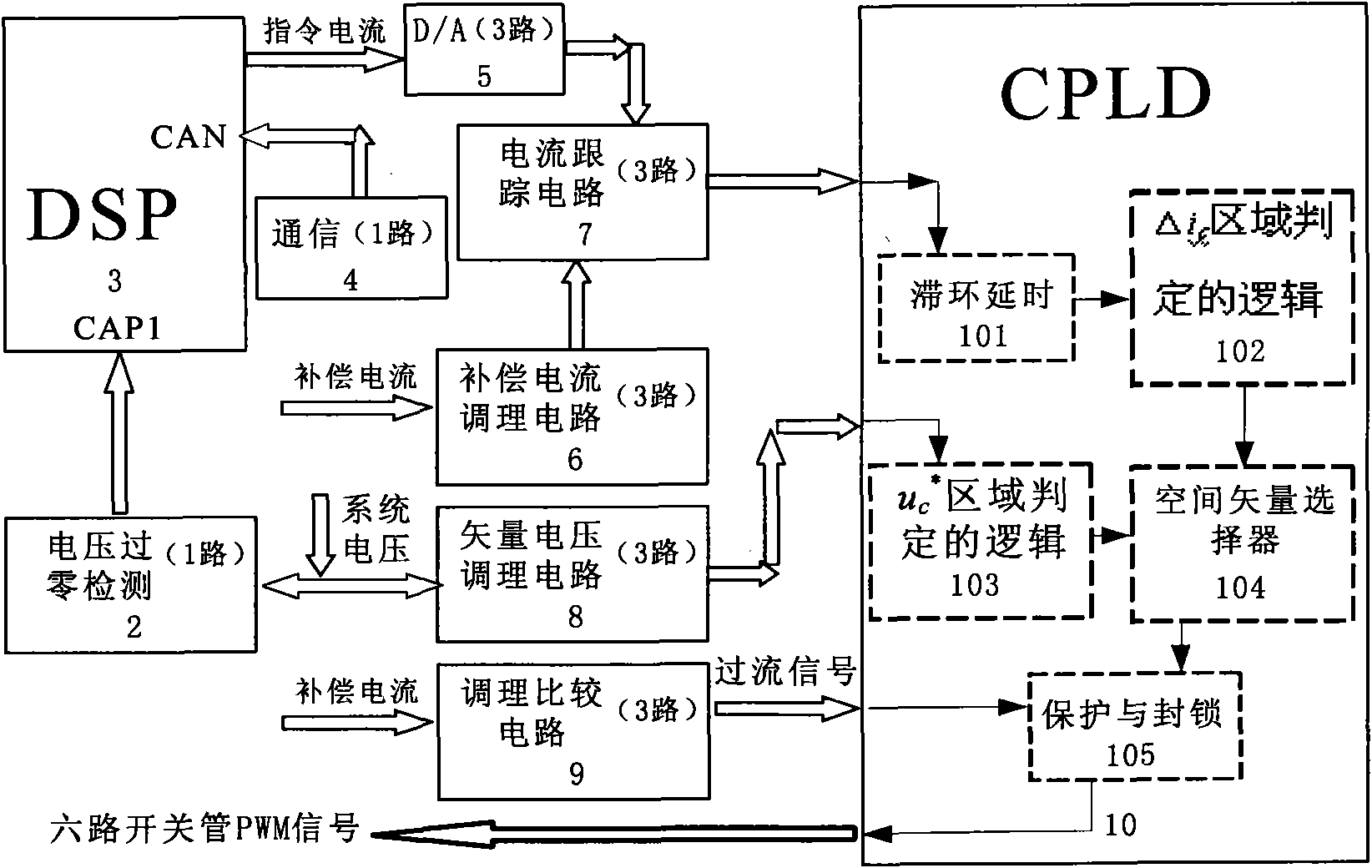
[0041] like figure 1 As shown, the inverter drive device based on DSP and CPLD includes microprocessor DSP3 and CPLD drive circuit 10, and also includes in the inverter drive device:

[0042] One A-phase voltage zero-crossing detection circuit 2, used to detect the fundamental wave zero-crossing signal of the power grid;

[0043] One CAN communication circuit 4, receiving instructions from the host computer, including instruction current;

[0044] The three-way Hall voltage sensor circuit is used to detect the phase voltage of the three-phase circuit;

[0045] The three-way Hall current sensor circuit is used to detect the compensation current of the three-phase circuit, that is, the output current of the three-phase inverter;

[0046]Three-way D / A conversion circuit 5, DSP 3 sends three-way digital command current signals to the command current received by DSP 3 through the theore...


PUM


Abstract

The invention relates to an inverter driving device based on a digital signal processor (DSP) and a complex programmable logic device (CPLD). The inverter driving device comprises the DSP and CPLD driving circuit of an embedded type microprocessor, a one-path A-phase voltage zero passage detecting circuit, a one-path controller area network (CAN) communication circuit, a three-path Hall voltage sensor circuit, a three-path Hall current sensor circuit, a three-path D / A switching circuit, a three-path compensating current adjusting circuit, a three-path current tracing circuit and a three-path vector voltage adjusting circuit, wherein the DSP circuit sends three digital command current signals converted into three simulated command current signals with the difference of 120 degree and the same compensating current frequency through the three-path D / A switching circuit; the three-path compensating current adjusting circuit adjusts three-phase compensating current detected by three-path Hall current sensor circuit into appropriate compensating current signals; the three-path current tracing circuit compares the three simulated command current signals and the current generated by the three-path compensating current adjusting circuit to obtain three current tracing and comparing signals; and the three-path vector voltage adjusting circuit adjusts the phase voltage detected by the three-path Hall voltage sensor circuit into signals of a region in which the vector voltage is positioned.

Description

technical field [0001] The present invention relates to a multi-level inverter driving device, in particular to an embedded microprocessor DSP as a control circuit, and a complex programmable logic device CPLD (Complex Programmable Logic Device) as a driving circuit, that is, based on CPLD technology, using current The spatial distribution of the deviation vector (current deviation change rate vector) is used to give the best voltage vector switching, so that the current deviation is controlled within the hysteresis width to realize the drive signal of the inverter circuit. The device can be used in reactive power compensation, active filtering, switching power supply, motor speed control, inverter, ultrasonic generator, charger and other fields. Background technique [0002] In recent years, the frequency conversion technology with the inverter circuit as the core has been continuously improved, and the application of frequency conversion technology has increased, which has...

Claims


Application Information

Patent Timeline
Patent Type & Authority Applications(China)
IPC IPC(8): H02M7/48H02H7/122
Inventor 孙运全孙玉坤尹强茅靖峰
Owner JIANGSU UNIV
Why Eureka
Try Eureka