
Device and method for blow moulding plastic containers

A plastic container and blow molding technology, applied in the field of blow molding plastic containers

Active Publication Date: 2011-03-23
KRONES AG
View PDF8 Cites 4 Cited by
  • Summary
  • Abstract
  • Description
  • Claims
  • Application Information

AI Technical Summary

Problems solved by technology

The plug-in fluid connector also does not spatially secure the detached connector

Method used


Image

  • Device and method for blow moulding plastic containers
  • Device and method for blow moulding plastic containers
  • Device and method for blow moulding plastic containers

Examples


Embodiment Construction

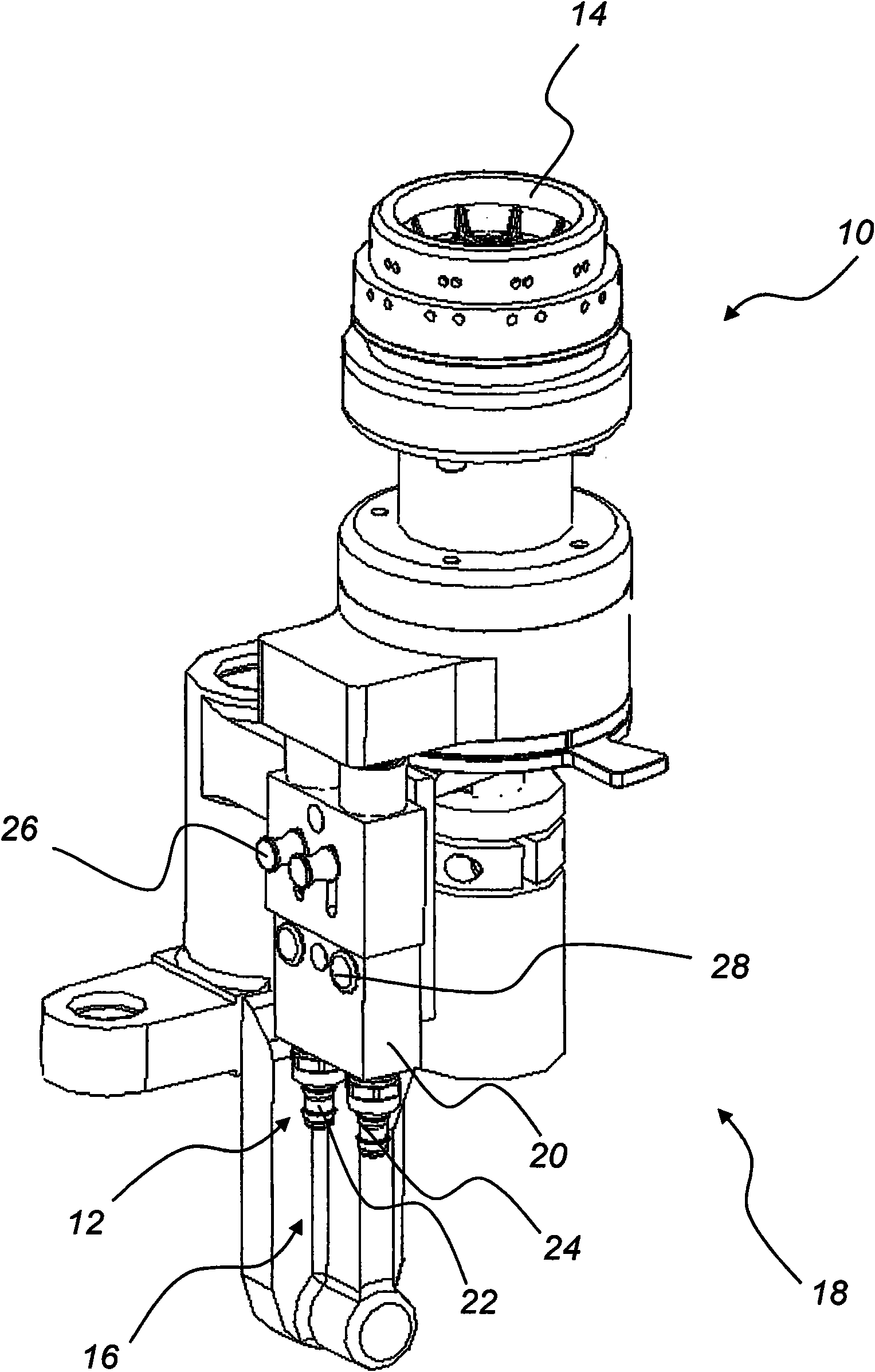
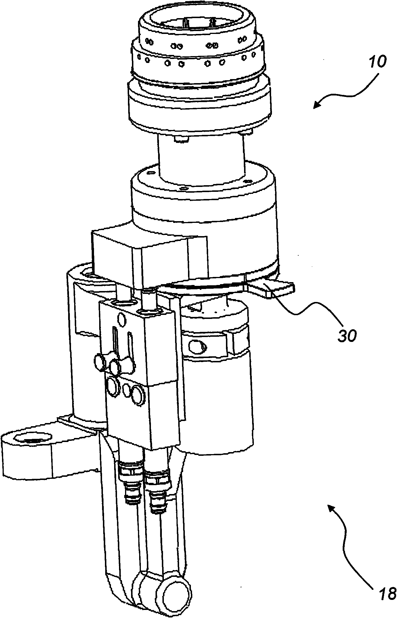
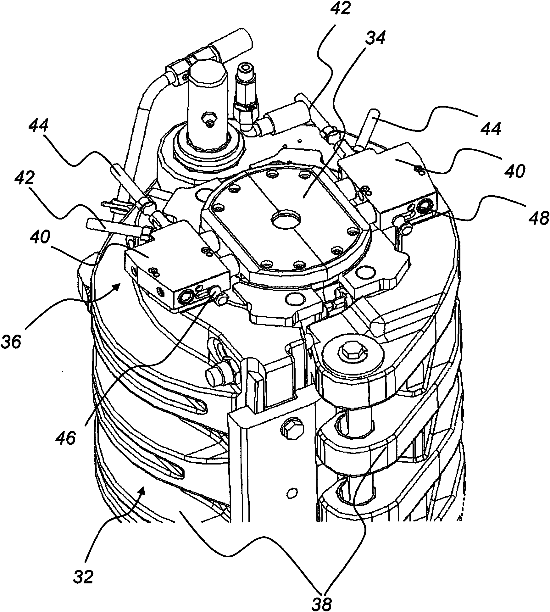
[0040] by means of Figure 1 to Figure 4 The schematic diagram in illustrates the function of the apparatus for blow molding beverage containers or plastic bottles and the method for changing individual blow moulds.

[0041] figure 1 with figure 2 The schematic perspective view in shows a base 10 of a device for blow molding plastic containers, which is only partially shown. image 3 with Figure 4 A half shell of a blow mold is shown. The half-shells are openable laterally and the bottom shape 14 of the base 10 can be pressed towards the lower front side of the half-shells. at the same time, figure 1The illustration in shows a situation where a fluid connection 12 is bonded to a base 10 to supply cooling fluid to the base 10, figure 2 The fluid connection 12 is shown detached. The bottom shape 14 includes integrated fluid tubes (not shown) for tempering the bottom shape 14 during blow molding or stretch blow molding of the plastic container. The coolant fluid tubes ...


PUM


Abstract

The invention relates to a device and a method for blow moulding plastic containers. A device for blow molding plastic containers includes an openable and closable blow mold for the conversion of tempered plastic preforms, whereby an inner blow pressure is applied to the plastic containers. The blow mold contains at least two shell like blow mold pieces that are arranged interchangeably at a blow mold carrier and that each contains cooling fluid pipes as conducts for a cooling fluid extending therein to temper the blow mold during and / or after blow molding of the plastic containers. The cooling fluid pipes in the blow mold are connected to a central cooling fluid supply. A coupling module that is associated with the blow mold carrier is arranged between the central cooling fluid supply and the cooling fluid pipes extending in the blow mold pieces. The coupling module and the blow mold carrier are associated spatially and / or structurally.

Description

technical field [0001] The invention relates to a device for blow molding plastic containers, which device is characterized in that the device comprises an openable and closable blow mold for plastic preforms by applying internal blow pressure to the The tempered plastic preforms are thus transformed into plastic containers. The invention also relates to a method for blow molding plastic containers. Background technique [0002] During the production of plastic containers for drinking liquids, high temperatures are used to cause the preforms to be reshaped in blow molds or stretch blow molding units. For blow molding, suitable blow molds made of several parts are used. Typically, such blow molds are made of two parts that can pivot relative to each other and a base that slides against closed blow mold pieces. The temperature change during blow molding or stretch blow molding is accomplished by cooling fluid that is directed through fluid pipes in the blow molded part. Th...

Claims


Application Information

Patent Timeline
Patent Type & Authority Applications(China)
IPC IPC(8): B29C49/48B29C33/04
CPCB29C49/42B29C2049/4858B29C49/4823B29C33/306B29C33/04B29C2049/4856Y10T29/49815Y10T29/49826
Inventor 克里斯汀·斯多波托马斯·菲利普
Owner KRONES AG
Learn More