AI technical title is built by Patsnap AI team. It summarizes the technical point description of the patent document.
A technology of roving frame and roving bobbin, applied in the directions of transportation and packaging, textile and papermaking, thin material processing, etc., can solve the problems of short doffing time and difficulty in installing roving frame.
Active Publication Date: 2011-03-23
SAURER GERMANY GMBH & CO KG
View PDF10 Cites 18 Cited by
Summary
Abstract
Description
Claims
Application Information
AI Technical Summary
This helps you quickly interpret patents by identifying the three key elements:
Problems solved by technology
Method used
Benefits of technology
Problems solved by technology
[0015] The bobbin changing device for roving frames described in DE 10 2006 024 553 B4 is characterized by short doffing times and has been very successful in practice, but has the disadvantage of being difficult to install on existing roving frames
Method used
Image
Click on the blue label to locate the original text in one second.
Reading with bidirectional positioning of images and text.
Examples
Embodiment Construction
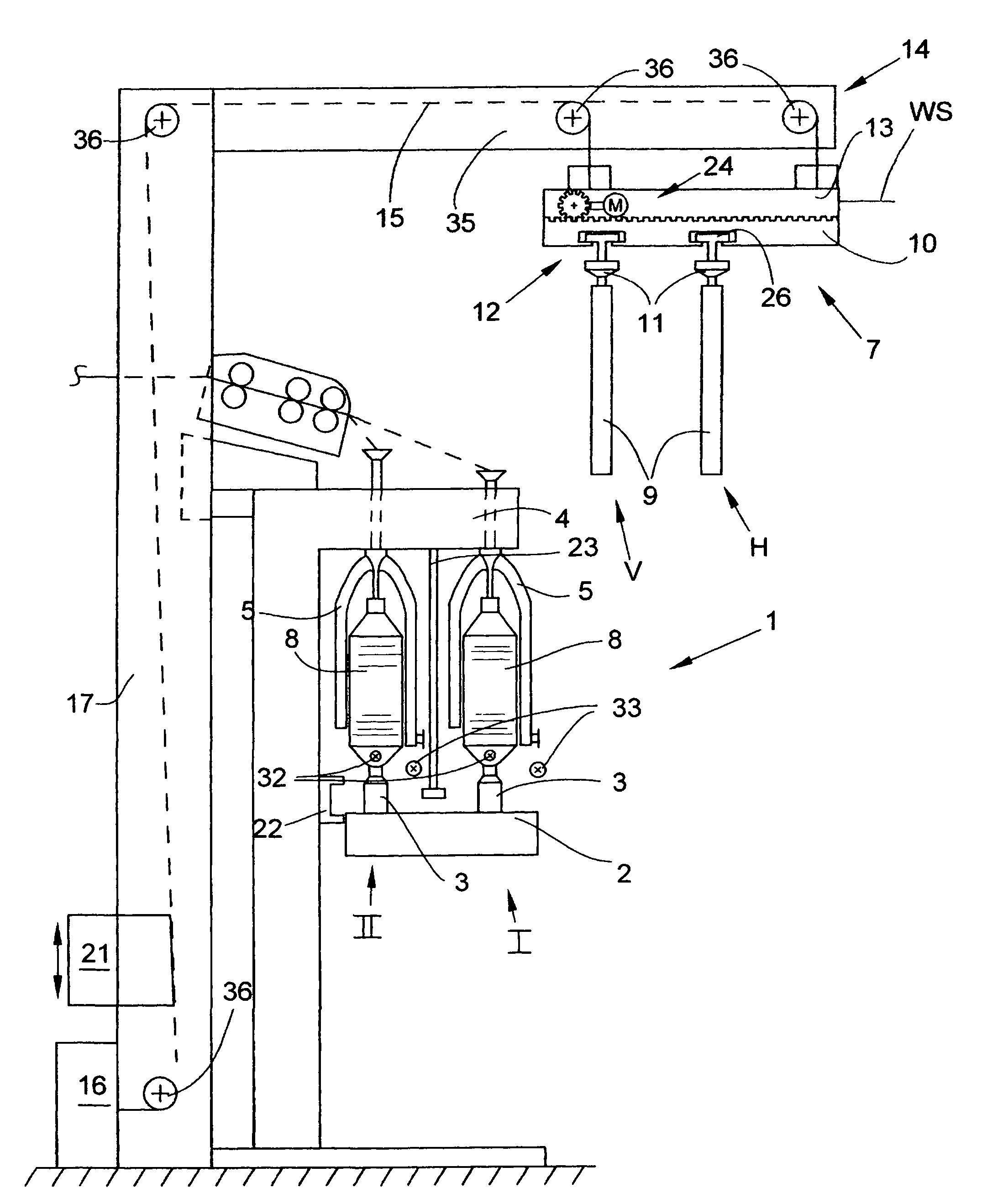
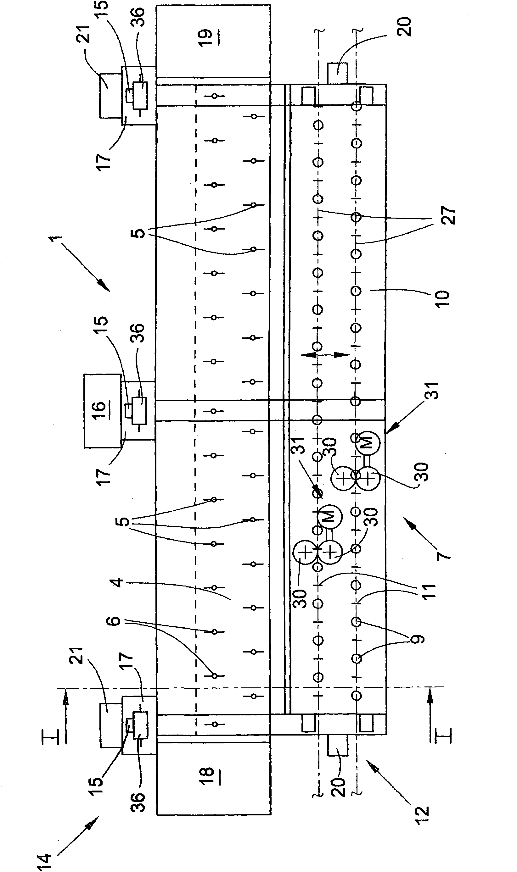
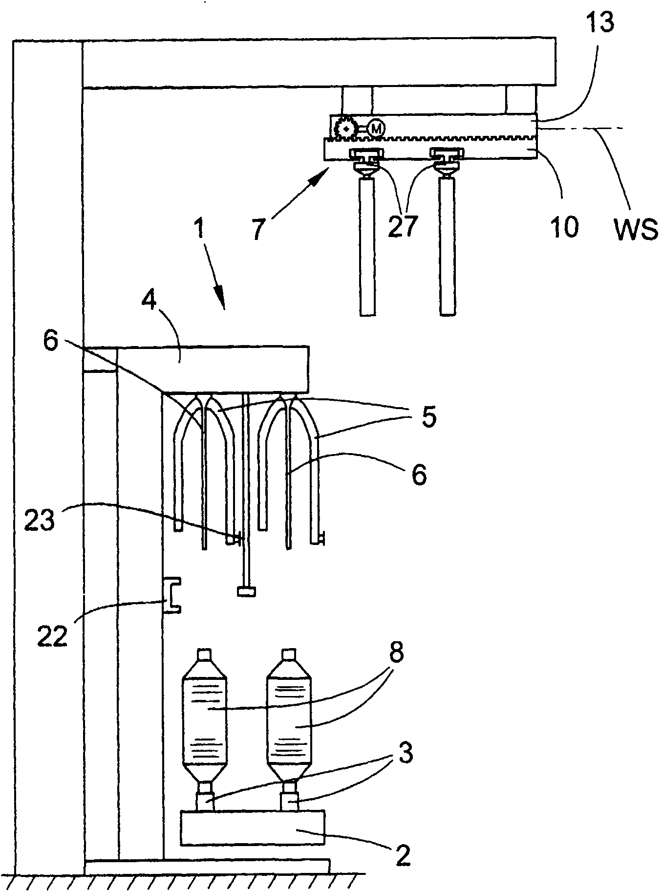
[0052] figure 1 A roving frame 1 is shown with a vertically displaceably mounted bobbin rail 2 and a fixedly arranged flyer rail 4 between end frames 18 , 19 . The flyers 5 of the flyer rail 4 each have a longer central spindle bar 6 , while the bobbin holders 3 arranged in the region of the bobbin rail 2 are shorter. The roving frame 1 is spanned by an external frame structure 14 which is a part of the bobbin changing device 7 according to the invention. It can be seen that, especially from figure 1 with 2 It can be seen that the frame structure 14, which is preferably designed as a hanger structure, has a rear support 17 and a horizontal bracket 35, in the region of the free end of which the base element 13 of the bobbin changing device 7 is articulated via a traction device 15. , so that the base element 13 is vertically adjustable. In other words, the base element 13 is connected to the drive device 16 via the traction device 15 , which is guided by the deflection whee...
PUM
Abstract
The present relates to a reel change device for a roving machine. The roving machine is provided with a bobbin rail which can be equipped with a mode that the vertical shifting is allowed, and is provided with a flyer rail which is fixedly equipped. The flyers of the flyer rail are respectively provided with a central spindle blade. The reel change device is provided with a replacement platform which is movably equipped and is provided with a transport mechanism. The transport mechanism is provided with a tube support which is used for suspending and conveying roving bobbins and hollow bobbins. The reel change device (7) is provided with a base component (13) which can be adjusted vertically. The base component is connected with an outer frame structure (14) which bestrides the roving machine (1). A change platform (10) is configured on the base component (13) and can move into the riving machine (1) from a front surface so the hollow tube supports (11) of the conveying mechanism (12) and the tube supports (11) equipped with the hollow bobbins can be positioned to accurately preset positions in the area of the bobbin rail (2). The conveying mechanism (12) is composed of an annular conveyor (26) or two suspension type frame sets (27).
Application Information
Patent Timeline
Application Date:The date an application was filed.
Publication Date:The date a patent or application was officially published.
First Publication Date:The earliest publication date of a patent with the same application number.
Issue Date:Publication date of the patent grant document.
PCT Entry Date:The Entry date of PCT National Phase.
Estimated Expiry Date:The statutory expiry date of a patent right according to the Patent Law, and it is the longest term of protection that the patent right can achieve without the termination of the patent right due to other reasons(Term extension factor has been taken into account ).
Invalid Date:Actual expiry date is based on effective date or publication date of legal transaction data of invalid patent.

