Roving machine with reel change mechanism

A technology of roving frame and bobbin rail, which is applied in textile and papermaking, thin material processing, conveying filamentous materials, etc. bootstrap effect

Active Publication Date: 2011-03-23
SAURER GERMANY GMBH & CO KG
View PDF7 Cites 8 Cited by
  • Summary
  • Abstract
  • Description
  • Claims
  • Application Information

AI Technical Summary

Problems solved by technology

As a result, each coarse / empty tube change is relatively time-consuming, which has a negative effect on the overall efficiency of the roving frame

Method used


Image

  • Roving machine with reel change mechanism
  • Roving machine with reel change mechanism
  • Roving machine with reel change mechanism

Examples


Embodiment Construction

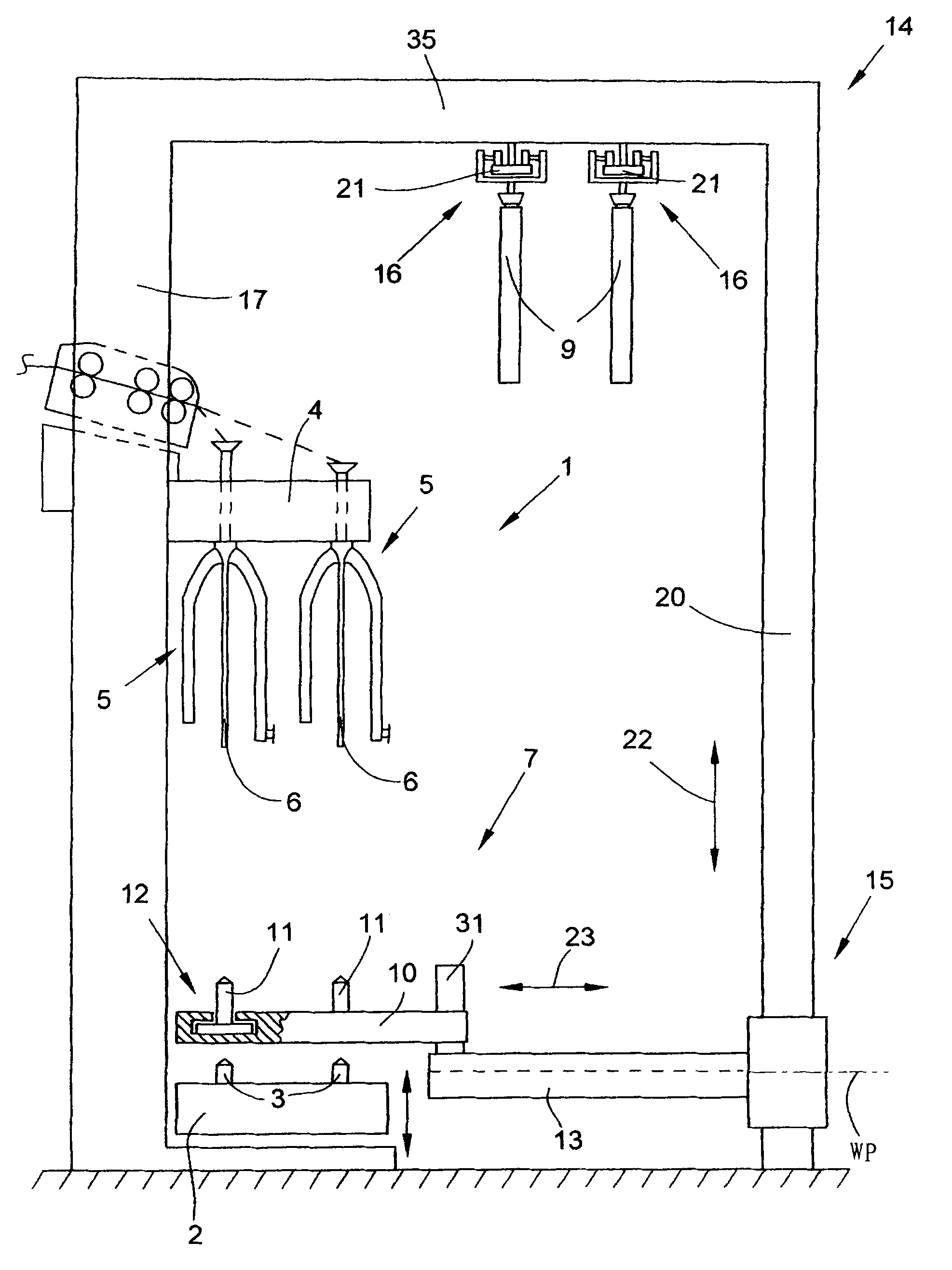
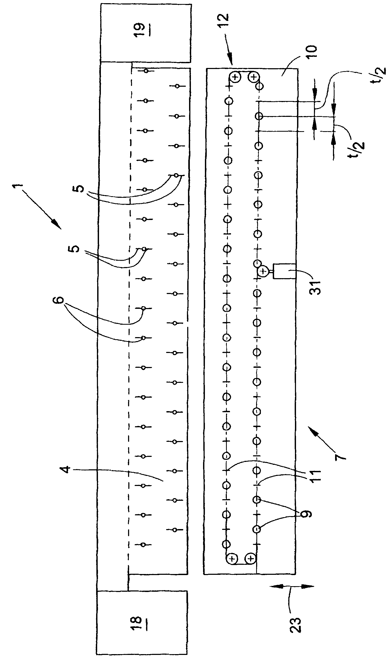
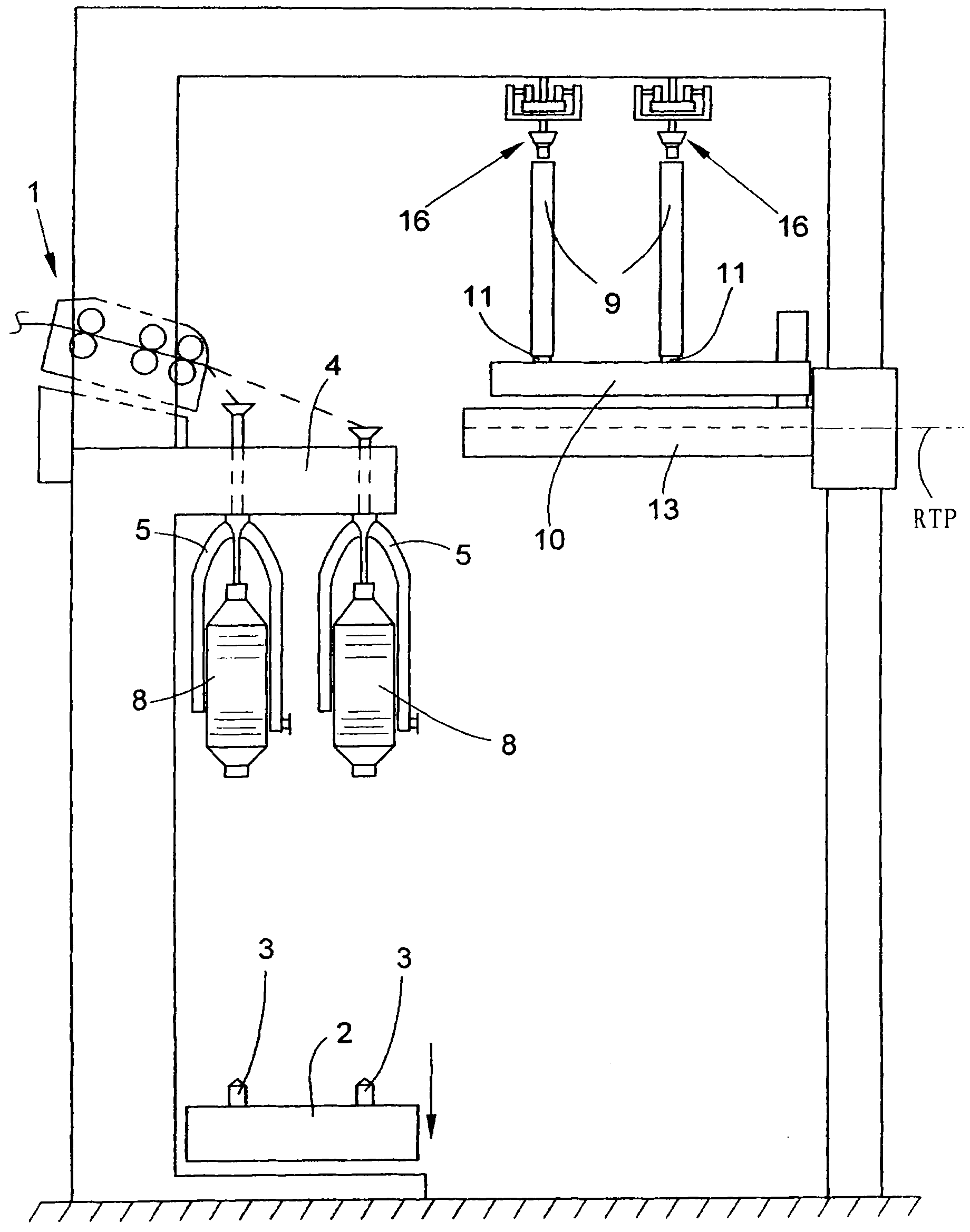
[0024] figure 1 A roving frame 1 is shown in , which has a bobbin rail 2 mounted displaceably in the vertical direction and a fixedly arranged flyer rail 4 between end frames 18 , 19 . The flyers 5 of the flyer rail 4 each have a relatively long central spindle 6 , while the bobbin holders 3 arranged in the region of the bobbin rail 2 are relatively short. A frame structure 14 spans the roving frame 1 , on which the can changer 7 according to the invention is guided in a vertically displaceable manner. as from figure 1 It can be seen that the frame structure 14 is configured as a gantry structure, in other words, the frame structure 14 has a rear support column 17, a front support column 20 and a horizontal frame 35, in the region of the horizontal frame 35 there are provided for Rail member 21 of suspended carrier 16 . The base element 13 of the can changing mechanism 7 is hinged on at least two front support columns 20 , for example via slide guides 15 , so that the base ...


PUM


Abstract

The present invention relates to a roving machine with a bobbin rail, a flyer rail and a reel change mechanism. The bobbin rail can be equipped with movably in a vertical direction. The flyer rail is equipped fixedly. All flyers of the flyer rail are respectively provided with a central spindle. The reel change mechanism is connected with a frame structure which bestrides the roving machine. The reel change mechanism is provided with a base component which is movable in a vertical direction relatively to the adjustment height. The base component is provided with a change platform which is equipped movably in a horizontal direction. According to the invention, the change platform (10) is provided with a conveying device (12) which is provided with a case carrier (11) for receiving roving reels (8) or empty bobbins (9). Furthermore the conveying device (12) can be positioned in an area of the roving machine (1) such that empty case carriers (11) or case carriers (11) provided with the empty bobbins (9) are alternatively positioned exactly below central spindles (6) of a flyer (5) of the flyer rail (4).

Description

technical field [0001] The present invention relates to a roving frame, more specifically, relates to a roving frame with bobbin rails, flyer rails and a bobbin changing mechanism, the bobbin rails are installed in a vertically movable manner, the flyer rails fixedly arranged, the flyers of the flyer rails are each equipped with a central spindle, the can changer is connected to a frame structure spanning the roving frame, the can changer has a vertically adjustable base element, the The base element has a replacement platform installed in a horizontally movable manner. Background technique [0002] It is known to process fiber slivers produced by means of so-called drafting frames and consisting of fiber materials arranged substantially in parallel on roving frames to form roving bobbins. In other words, on such roving frames, the still relatively thick fiber sliver fed out is drawn further and has a relatively low twist in order to ensure a high strength. The roving bobb...

Claims


Application Information

Patent Timeline
Patent Type & Authority Applications(China)
IPC IPC(8): D01H9/18D01H9/04B65H67/06
CPCD01H9/001D01H9/18D01H9/046
Inventor 卡尔-海因茨・麦克
Owner SAURER GERMANY GMBH & CO KG
Why Eureka
Try Eureka