Single-motor pneumatic oscillating arm of jig dyeing machine

A single-motor, dye-jigger technology, applied in the field of dye-jiggers

Inactive Publication Date: 2011-03-23
ZAOZHUANG FUYUAN ENVIRONMENTAL PROTECTION & ENERGY SAVING MACHINERY MFG CO LTD
View PDF0 Cites 10 Cited by
  • Summary
  • Abstract
  • Description
  • Claims
  • Application Information

AI Technical Summary

Problems solved by technology

The transmission chain transmits powe...

Method used


Image

  • Single-motor pneumatic oscillating arm of jig dyeing machine
  • Single-motor pneumatic oscillating arm of jig dyeing machine
  • Single-motor pneumatic oscillating arm of jig dyeing machine

Examples


Embodiment Construction

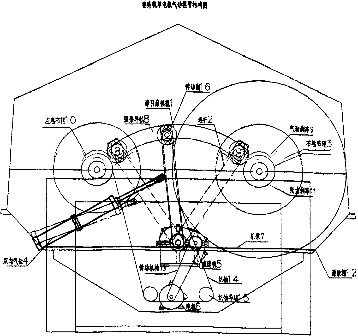
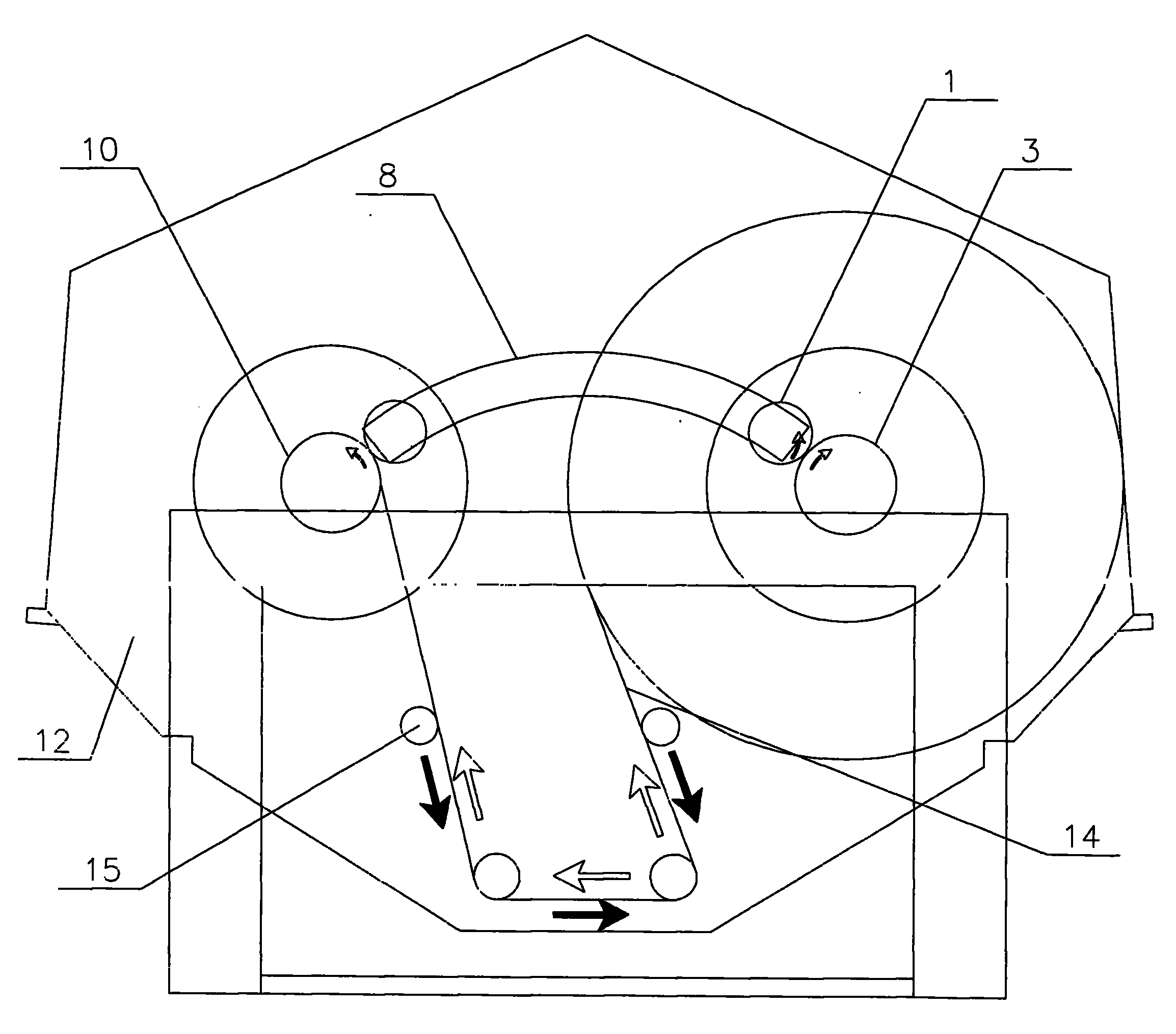
[0007] The present invention as figure 1 Shown, by frame 7, bleaching and dyeing tank 12, left fabric rolling roller 10, transmission mechanism 13, right fabric rolling roller 3, pneumatic brake 9, tension brake 11, fabric guide roller 15, arc guide rail 8, connecting rod 2, Composed of two-way cylinder 4, friction roller 1, reducer 5, motor 6 and so on. The motor 6 is connected to the speed reducer 5 by the transmission mechanism 13 and decelerates; as figure 1 , Shown in 5, there are assembly holes at connecting rod 2 two ends, and the assembly holes of two-way cylinder 4 guide rods are arranged between the assembly holes at connecting rod 2 two ends. One end assembly hole of the connecting rod 2 is assembled on the shaft end of the friction roller 1 , and the other end assembly hole of the connecting rod 2 is assembled on the output shaft of the reducer 5 . The transmission pair 16 transmits power between the reducer 5 and the friction roller 1 . The guide rod end of the...


PUM


Abstract

The invention discloses a single-motor pneumatic oscillating arm of a jig dyeing machine. The invention relates to the jig dyeing machine in the technical field of printing and dyeing machines. The existing jig dyeing machine uses double motors for reversing fabric, and the running speed of the fabric is non-constant. The single-motor pneumatic oscillating arm adopts the single motor for dragging, and the reversing function of the fabric 14 in a bleaching and dyeing pond 12 is completed by a transmission mechanism consisting of an arc-shaped guide rail 8, a connecting rod 2, a two-way cylinder 4 and a friction roller 1. Assembly holes are arranged at two ends of the connecting rod 2, a guide rod mounting hole for the cylinder 4 is arranged between the two assembly holes for connecting the cylinder 4, and the fulcrum of the cylinder 4 is fixed on a frame 7. The two ends of the connecting rod 2 are assembled at the shaft end of the friction roller 1 and an output shaft of a speed reducer 5. The arc-shaped guide rail 8 is mounted on the side wall, the connecting rod 2 can oscillate through expansion and contraction of the cylinder 4, and the friction roller 1 can slide along the arc-shaped guide rail 8 and be in close contact with cloth rollers 3 and 10 for compressing the fabric 14. A tension brake 11 can prevent relaxation of the fabric 14. The running speed of the fabric 14 can realize constant speed by linear speed of the friction roller 1, and the press dehydration role can reduce the number of times of bleaching and dyeing, thereby saving steam, water, electrical energy and auxiliaries.

Description

technical field [0001] The invention relates to the technical field of printing and dyeing machinery. Especially suitable for dyeing jiggers for rinsing and dyeing in the printing and dyeing industry. Background technique [0002] At present, the common open-width printing and dyeing equipment in the market mainly includes long-car pad dyeing machines and dyeing jiggers. The long car pad dyeing machine occupies a large area and requires a lot of one-time investment, so it is not suitable for small batch trial production and production of fabrics. The existing jiggers in the market are low in price, small in floor space, suitable for trial production and production in small batches, and meet the current market demand, and are welcomed by printing and dyeing manufacturers. However, at present, the jiggers produced at home and abroad all use a double-motor structure, which has three disadvantages: one is to increase the investment in motors and reducers, which increases the p...

Claims


Application Information

Patent Timeline
IPC IPC(8): D06B3/32D06B15/02D06B23/00D06B23/02D06B23/04
Inventor 孙有福
Owner ZAOZHUANG FUYUAN ENVIRONMENTAL PROTECTION & ENERGY SAVING MACHINERY MFG CO LTD
Why Eureka
Try Eureka