Method and device for cleaning an exhaust gas flow of a combustion engine

A technology of exhaust flow and internal combustion engine, which is applied in the field of exhaust flow and exhaust flow devices of exhaust gas booster internal combustion engines, and can solve the problems of reducing the proportion of nitrogen oxides and other issues

Active Publication Date: 2015-04-01
MAN TRUCK & BUS AG
View PDF9 Cites 0 Cited by
  • Summary
  • Abstract
  • Description
  • Claims
  • Application Information

AI Technical Summary

Problems solved by technology

However, it should be noted here that due to the thermodynamic NO / NO 2 The equilibrium is on the NO side, so the NO 2 The share in the total nitrogen oxides decreases with increasing temperature

Method used


Image

  • Method and device for cleaning an exhaust gas flow of a combustion engine
  • Method and device for cleaning an exhaust gas flow of a combustion engine
  • Method and device for cleaning an exhaust gas flow of a combustion engine

Examples


Embodiment Construction

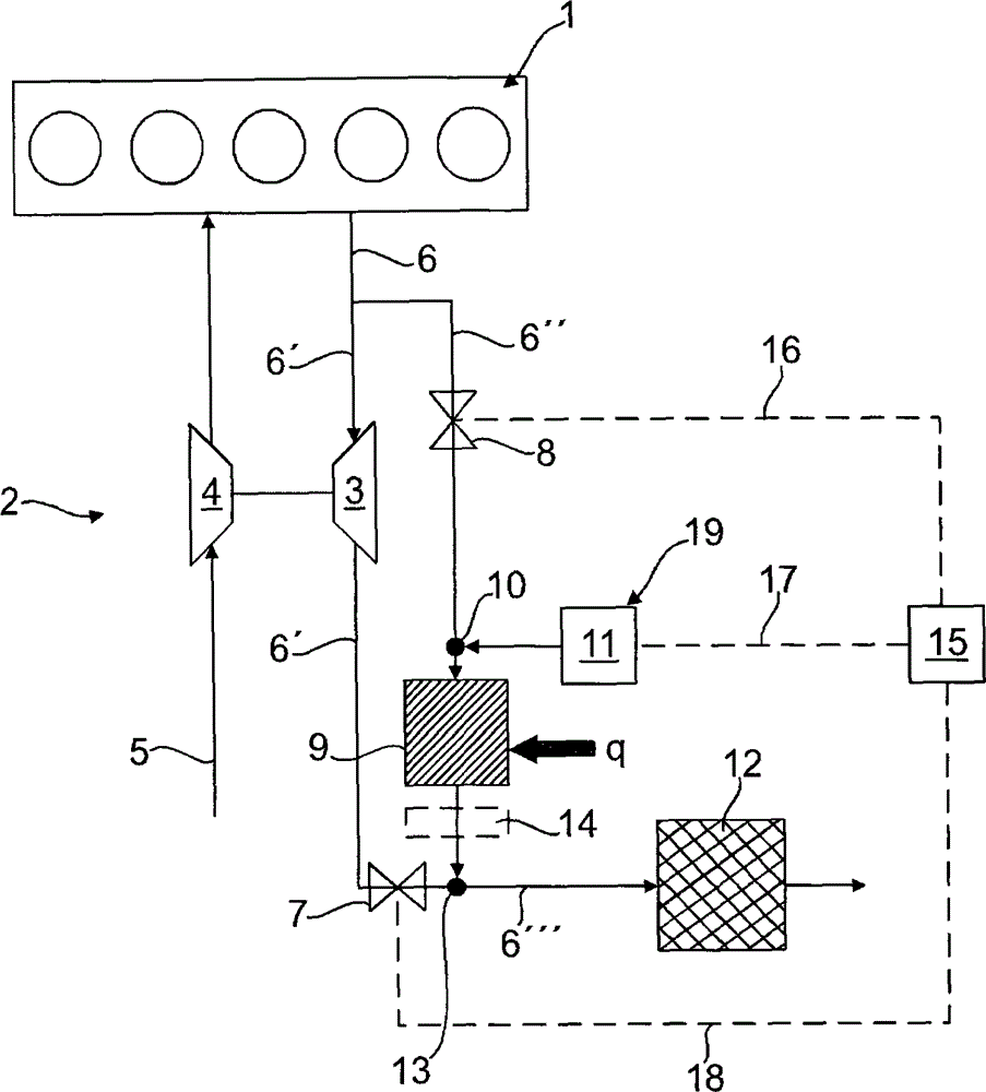
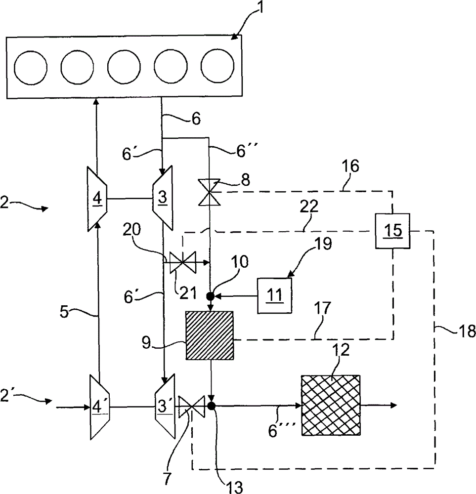
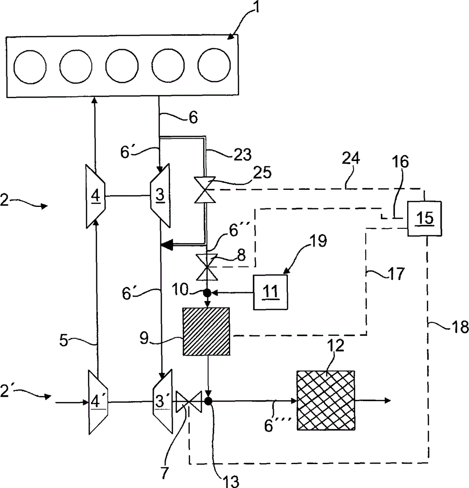
[0039] exist figure 1 2 schematically shows the use of the method according to the invention and a first embodiment of the device according to the invention for purifying the exhaust gas flow of a one-stage supercharged internal combustion engine 1 by means of an exhaust gas turbocharger 2 . The exhaust gas turbocharger 2 has an exhaust gas turbine 3 and a supercharger 4 . Charge air 5 is supercharged by means of supercharger 4 , wherein supercharger 4 is driven by means of exhaust gas turbine 3 .

[0040] Upstream of the exhaust gas turbine 3, the exhaust gas flow 6 from the internal combustion engine 1 branches into a main exhaust gas flow 6' and an exhaust gas partial flow 6". A variable throttle mechanism 7 configured as a valve. Viewed in the flow direction, a further variable throttle mechanism 8 is arranged in the exhaust gas subflow 6 ″. A reactor 9 is arranged downstream of the variable throttle 8 in the exhaust gas split 6 ″. Upstream of the reactor 9 there is a me...


PUM


Abstract

The method involves arranging a throttle device (8) in an exhaust gas partial flow (6''), and arranging another throttle device (7) in a main-exhaust gas flow (6'). The throttle devices are controlled by a controlling and / or regulating device based on reference exhaust gas amount and / or reference exhaust gas pressure and / or reference-air-fuel-ratio and / or reference exhaust gas temperature in the main flow and / or in the partial flow. The main flow is locked or throttled by the latter throttle device, and the partial flow is retained in a defined amount by the former throttle device. An independent claim is also included for a device for cleaning exhaust gas flow of an internal combustion engine.

Description

technical field [0001] The invention relates to a method according to the preamble of claim 1 for cleaning the exhaust gas flow of an internal combustion engine, in particular an exhaust gas supercharged internal combustion engine. The invention also relates to a device according to the preamble of claim 19 for cleaning the exhaust gas flow of an internal combustion engine, in particular an exhaust gas supercharged internal combustion engine. Background technique [0002] For exhaust gas purification, firstly the exhaust emissions from a cold start pose problems, since the legally prescribed exhaust emission limit values ​​must also be observed after a cold engine start and thus even when the catalytic converter has not yet reached operating temperature. Of great importance here is the so-called start-up temperature of the catalytic converter. The temperature at which the catalyst reached 50% conversion was indicated as the start-up temperature. Therefore, one of the objec...

Claims


Application Information

Patent Timeline
Patent Type & Authority Patents(China)
IPC IPC(8): F01N3/20F01N9/00F02B37/12
CPCF01N13/009F02B37/013F01N2410/06F01N2240/40F01N2900/08F01N3/2053F01N2610/10F02B37/004Y02T10/144F02D41/0007F01N2410/00F02D9/06Y02T10/24F02B37/18F01N3/208F01N2610/02Y02T10/12
Inventor A·多林
Owner MAN TRUCK & BUS AG
Why Eureka
Try Eureka