Method for breaking down fibrous material

A fiber material and decomposer technology, applied in the field of decomposing fiber materials, can solve problems such as low operating cost and the like

Active Publication Date: 2018-02-16
ANDRITZ AG
View PDF14 Cites 0 Cited by
  • Summary
  • Abstract
  • Description
  • Claims
  • Application Information

AI Technical Summary

Problems solved by technology

However, due to these measures the advantage of less operating costs compared to systems using mixers is lost

Method used


Image

  • Method for breaking down fibrous material
  • Method for breaking down fibrous material
  • Method for breaking down fibrous material

Examples


Embodiment Construction

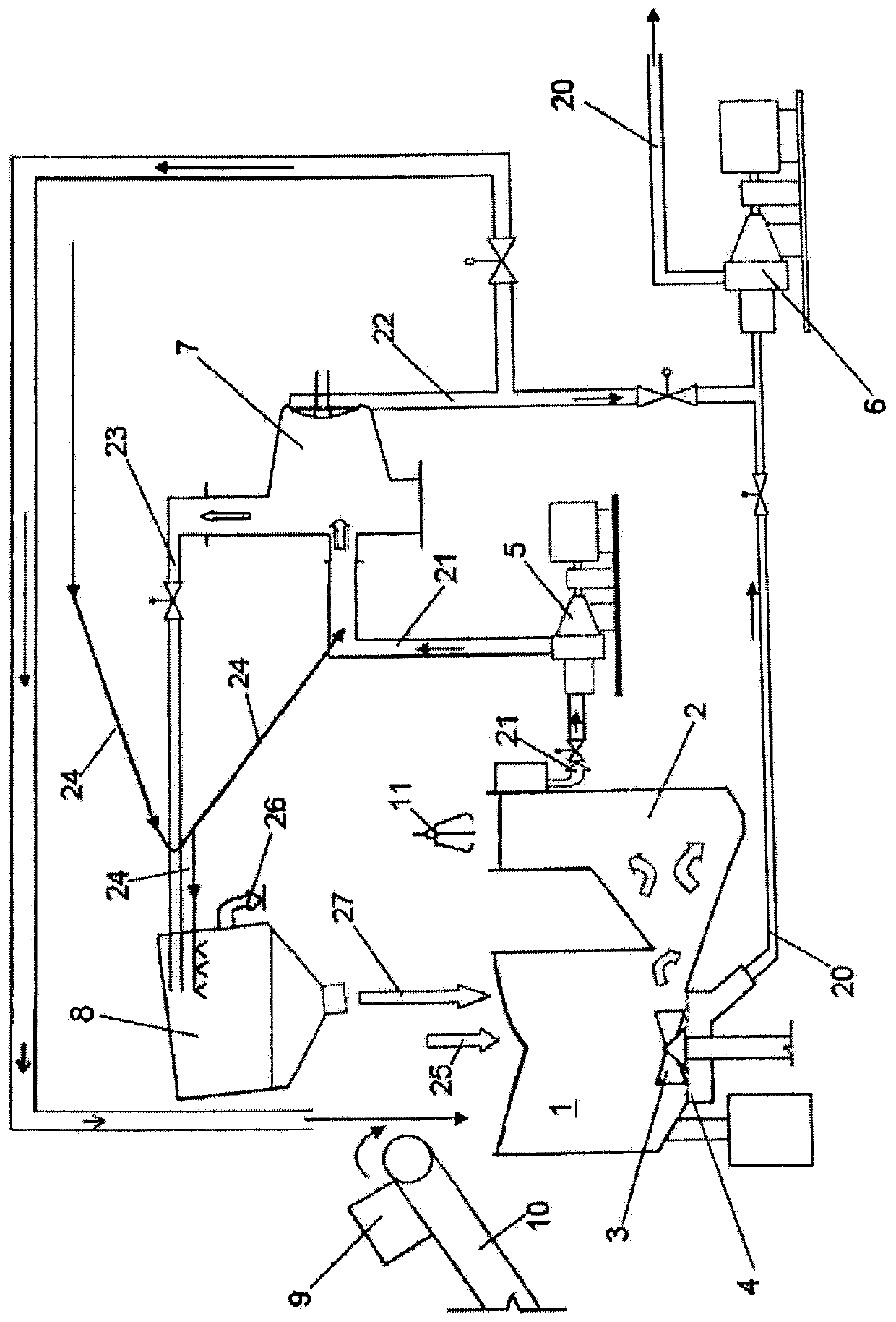
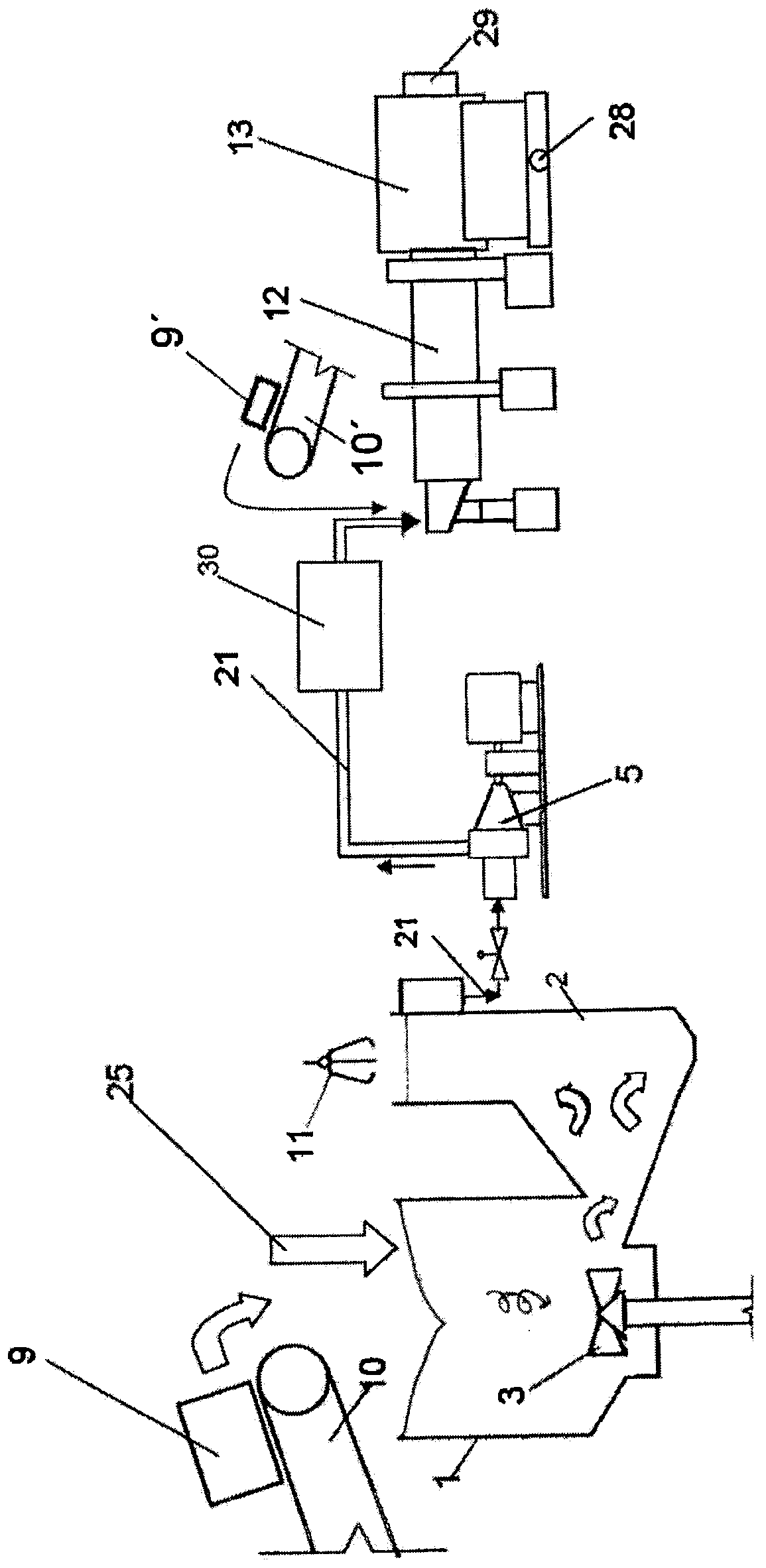
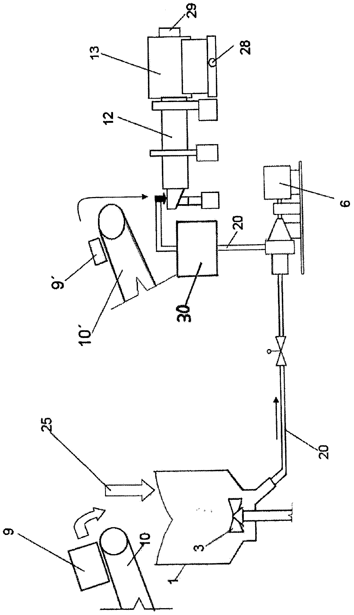
[0023] figure 1 A schematic diagram of a conventional method for decomposing waste paper is shown in . Here, the fibrous material 9 , ie the waste paper mass, is conveyed via a conveyor belt 10 to a material disintegrator 1 (mixer). The waste paper is mixed with water 25 in the material disintegrator 1 , where the waste paper is disintegrated and a fibrous material suspension is formed. In this case, the decomposition of the material in the mixer 1 is supported by the rotor 3 . Most of the decomposed fibers pass through the screen 4 below the rotor 3 to the product material chamber from which the product material flow 20 in the material decomposer 1 is output. The product material flow 20 is then conveyed by the product material pump 6 to further units for further processing.

[0024] A portion of the fibrous material suspension and in particular the disturbing material contained in the waste paper leaves the material disintegrator 1 as a slag stream 21 and reaches the sett...


PUM


Abstract

The invention relates to a method for decomposing a fiber material (9), and especially a method for decomposing waste paper. The fiber material (9) is transferred to a material decomposer (1) and is at least decomposed partly by mixing of a revolving member (3) and water (25). According to the method, after the material decomposer (1), at least a part (20,21,23) of the pre-decomposed fiber material (9) is transferred to a concentrator (30) used for concentration and a decomposition roller (12) used for further decomposition.

Description

technical field [0001] The subject of the invention is a method for decomposing fibrous material, in particular waste paper. Here, the fibrous material is fed to a low-concentration material disintegrator (mixer) where it is mixed with water by means of rotating elements and at least partially disintegrated. Background technique [0002] It has hitherto been customary, in particular in the treatment of waste paper, that the waste paper is decomposed in a material disintegrator (blender) and that the slag stream (Rejektstrom) in the material disintegrator is fed to a so-called waste processor, The fibrous material suspension is purified and deflated in the processor. The slag from the waste treatment machine, where it can already be prewashed, is usually conveyed cyclically to a washing drum, in which the slag is washed or dewatered. [0003] Depending on the use case, it is absolutely common to run multiple decomposition routes in parallel. Here, waste paper often has dif...

Claims


Application Information

Patent Timeline
Patent Type & Authority Patents(China)
IPC IPC(8): D21B1/32
CPCY02W30/64
Inventor 亚历山德·克沙伊德尔
Owner ANDRITZ AG
Why Eureka
Try Eureka