Single-plunger injection pump for pressure accumulating tube-fuel injection system

A fuel injection system and injection pump technology, which is applied in the direction of fuel injection pumps, fuel injection devices, charging systems, etc., can solve problems such as injection, and achieve the effects of reduced leakage, reasonable cost, and a small number of parts

Inactive Publication Date: 2008-09-24
ROBERT BOSCH GMBH
View PDF8 Cites 0 Cited by
  • Summary
  • Abstract
  • Description
  • Claims
  • Application Information

AI Technical Summary

Problems solved by technology

Due to the large temporary delivery volume and the resulting torque peaks as well as the hitherto unresolved problem of filling the pump cylinder in a very short time, no single-piston injection pumps have hitherto been used for common use in internal combustion engines with more than one cylinder. rail fuel supply

Method used


Image

  • Single-plunger injection pump for pressure accumulating tube-fuel injection system
  • Single-plunger injection pump for pressure accumulating tube-fuel injection system
  • Single-plunger injection pump for pressure accumulating tube-fuel injection system

Examples


Embodiment Construction

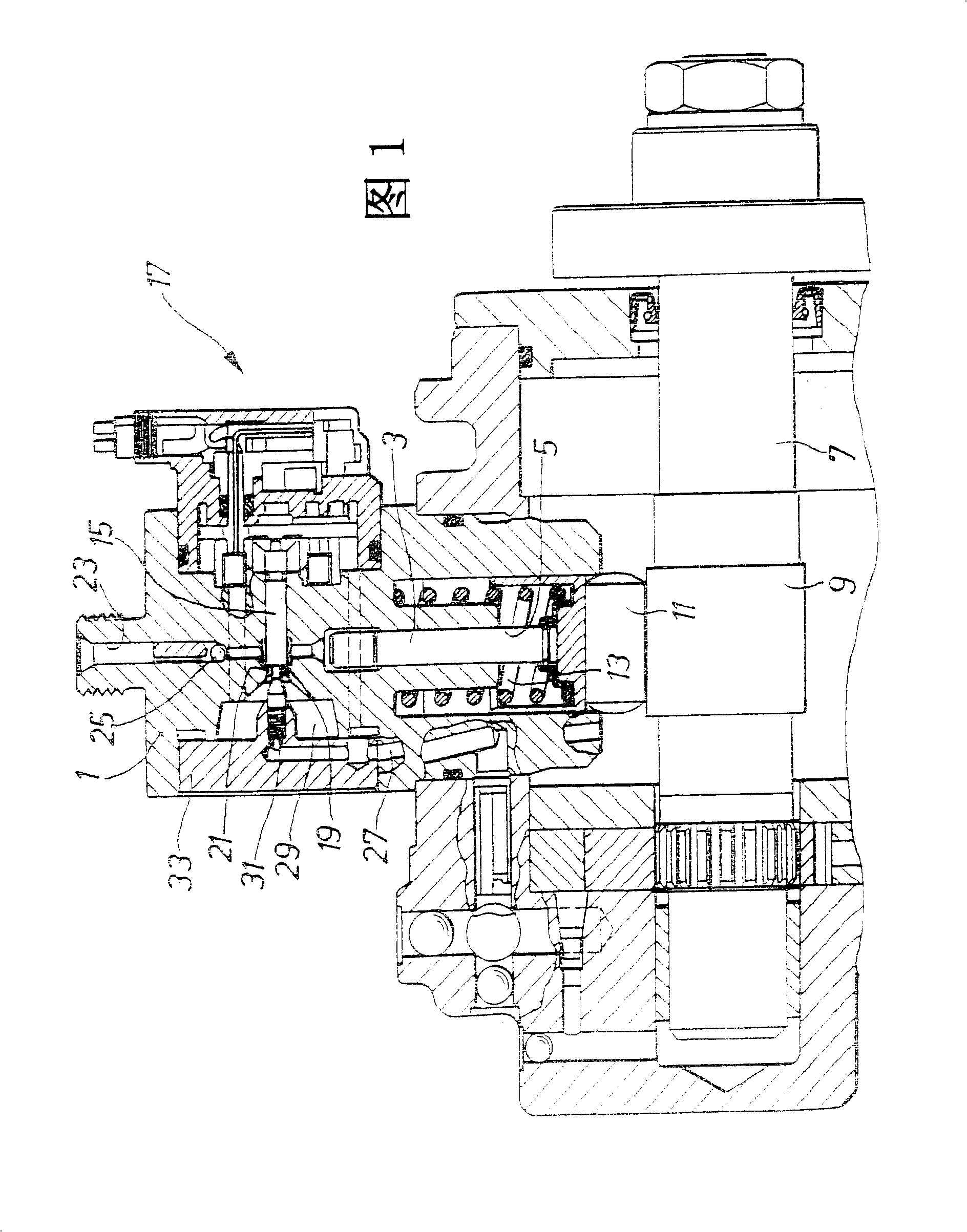
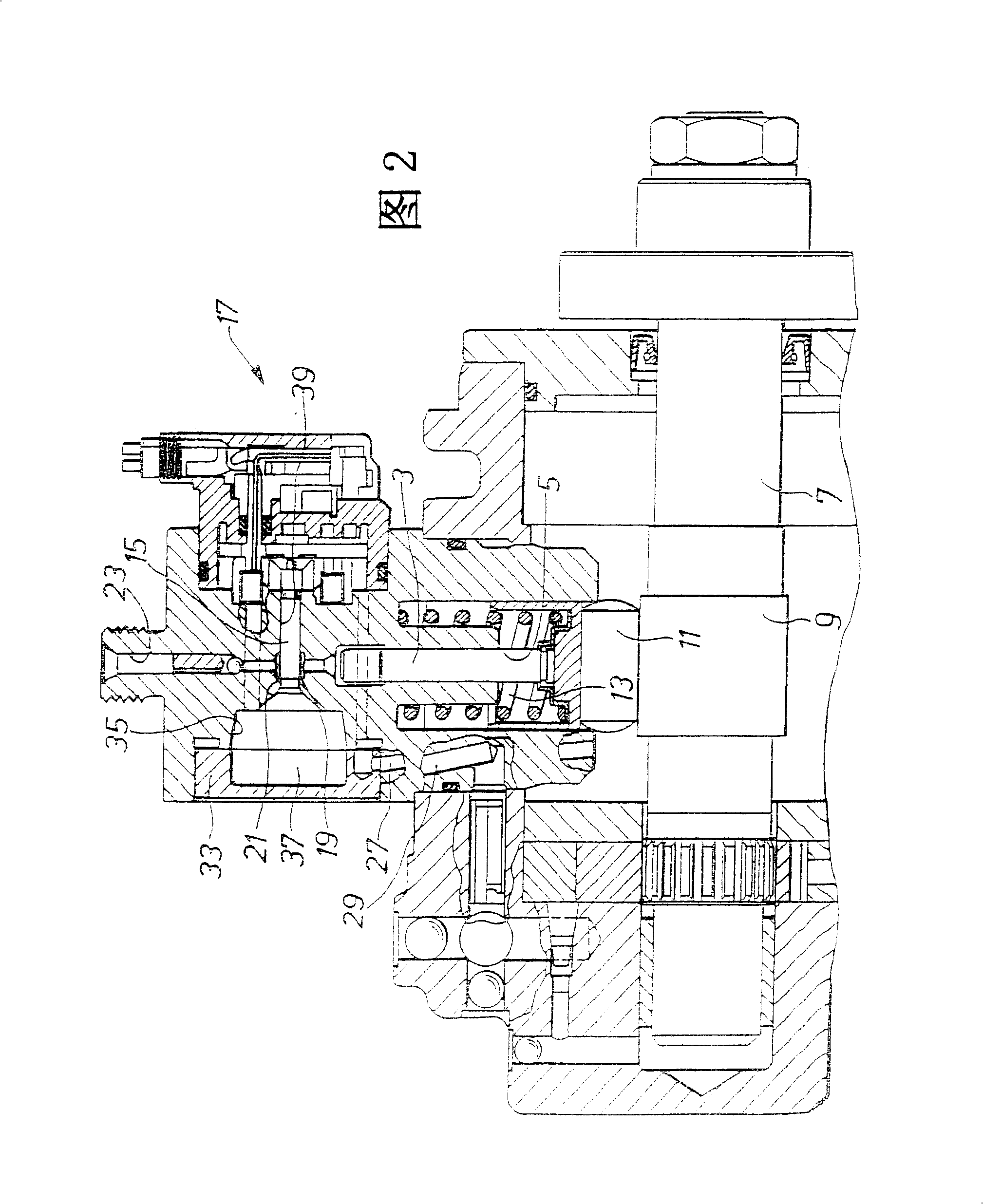
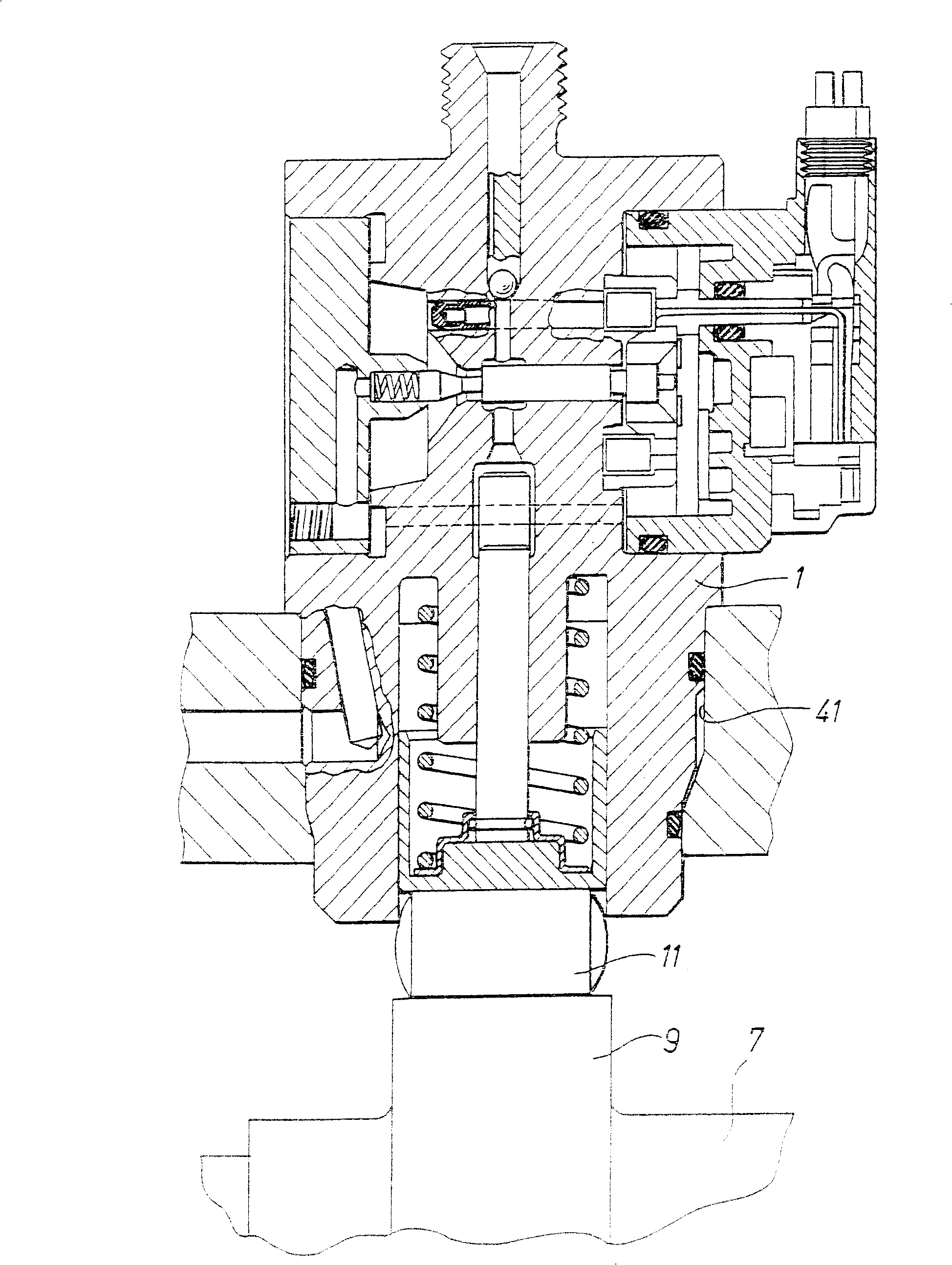
[0025] Figure 1 shows a first embodiment of a single plunger jet pump according to the invention. In a housing 1 a plunger 3 is guided by a pump cylinder 5 . The plunger 3 is driven by a camshaft 7 . An eccentric section 9 of the camshaft 7 acts on the plunger 3 via a push roller 11 . The eccentric section 9 is a cam in the sense of the invention. However, the cam can also have other geometries than an eccentrically arranged circle. The plunger 3 is pressed against the push roller 11 by means of a return spring 13 indicated only schematically.

[0026] Arranged in the housing 1 above the pump cylinder 5 is a control piston 15 as a flow control valve 17 designed as a solenoid valve, which is perpendicular to the longitudinal axis of the pump cylinder 5 . The control piston 15 has a shoulder 19 which forms a sealing seat with a correspondingly formed cam 21 . When the flow control valve 17 is closed, the shoulder 19 seats on the boss 21 and the fuel delivered by the plunger...


PUM


Abstract

The invention relates to a single-plunger injection pump for high-speed internal combustion engines which, due to its compact design and to its good volumetric efficiency in conjunction with a high oscillation frequency of the piston, has a flow rate comparable to that of a multi-plunger injection pump without the torque peaks becoming impermissibly high during actuation of the single-plunger injection pump.

Description

technical field [0001] The invention relates to an injection pump for a common rail fuel injection system of an internal combustion engine, which has a pump cylinder arranged in a housing and a plunger oscillating in the pump cylinder, wherein the fuel is sucked into the pump cylinder from the fuel inlet The pressure of the fuel is increased by the plunger, and has a flow control valve, wherein the flow control valve has a directly controlled control piston integrated in the housing, wherein the flow control valve sends the plunger to an outlet or to The delivery flow is controlled by a high pressure port connected to the common rail. Background technique [0002] The injection pump known from DE-OS 42 21 921 A1 is only suitable for use in an internal combustion engine with more than one cylinder if it has a number of pump cylinders corresponding to the number of cylinders. As the number of pump cylinders increases, the manufacturing cost also increases. [0003] In so-cal...

Claims


Application Information

Patent Timeline
Patent Type & Authority Patents(China)
IPC IPC(8): F04B49/24F02M63/02F02M59/20F02M51/00F02M59/02F02M59/10F02M59/44F04B9/04
CPCF02M59/02F04B49/243F04B2201/0207F04B2203/0605F02M63/0225
Inventor 瓦尔特·富克斯
Owner ROBERT BOSCH GMBH
Why Eureka
Try Eureka