Small bearing rivet cage decomposition mold and its decomposition method

A bearing cage and cage technology, applied in the field of bearings, can solve the problems of knocking on inner and outer rings, secondary scars, and inability to be used as genuine products, so as to improve accuracy and authenticity rate, avoid secondary scars, and solve problems that are not easy to decompose Effect

Active Publication Date: 2015-10-28
NINGBO DAER MACHINERY TECH CO LTD
View PDF6 Cites 0 Cited by
  • Summary
  • Abstract
  • Description
  • Claims
  • Application Information

AI Technical Summary

Problems solved by technology

[0005] The Chinese patent document discloses the authorized announcement number CN202263886U, and the utility model name is "railway locomotive bearing rivet riveting positioning device". The structure involved in the patented technical solution is relatively simple, and the stability performance is not optimal, so it is difficult to satisfactorily solve the bearing rivet riveting positioning technical issues
These processes are easy to damage the inner and outer rings of the bearing, forming secondary scars, resulting in inaccurate quality analysis of small bearings, and the damaged inner and outer rings of the bearing cannot be used as genuine products. Therefore, these dismantling processes in the past were unscientific, and it is urgent to develop a new one. Bearing rivet cage decomposition mold

Method used


Image

  • Small bearing rivet cage decomposition mold and its decomposition method
  • Small bearing rivet cage decomposition mold and its decomposition method
  • Small bearing rivet cage decomposition mold and its decomposition method

Examples


Embodiment Construction

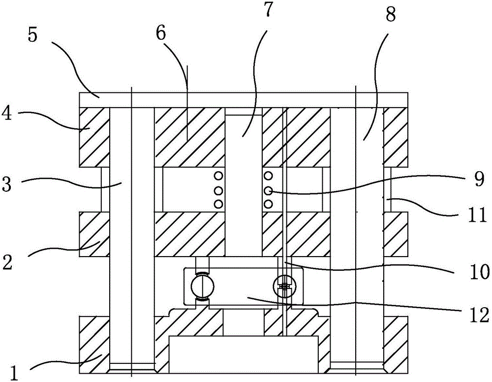
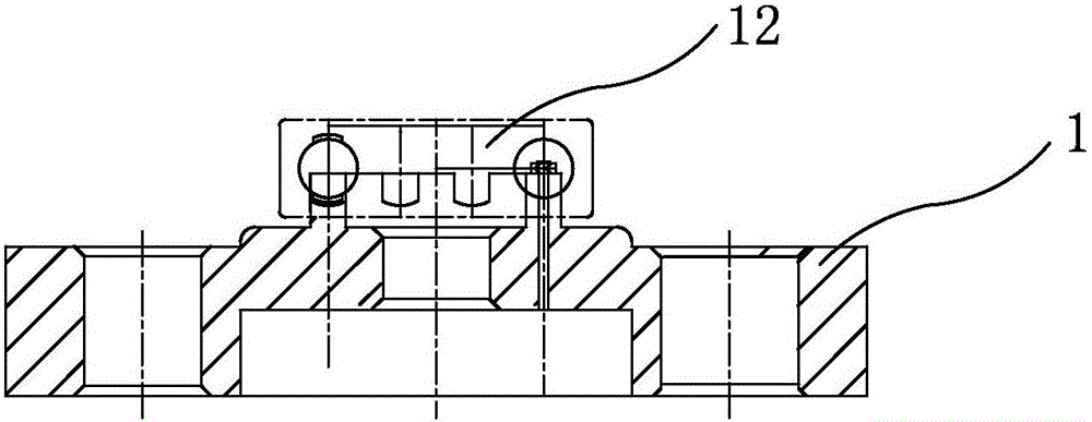
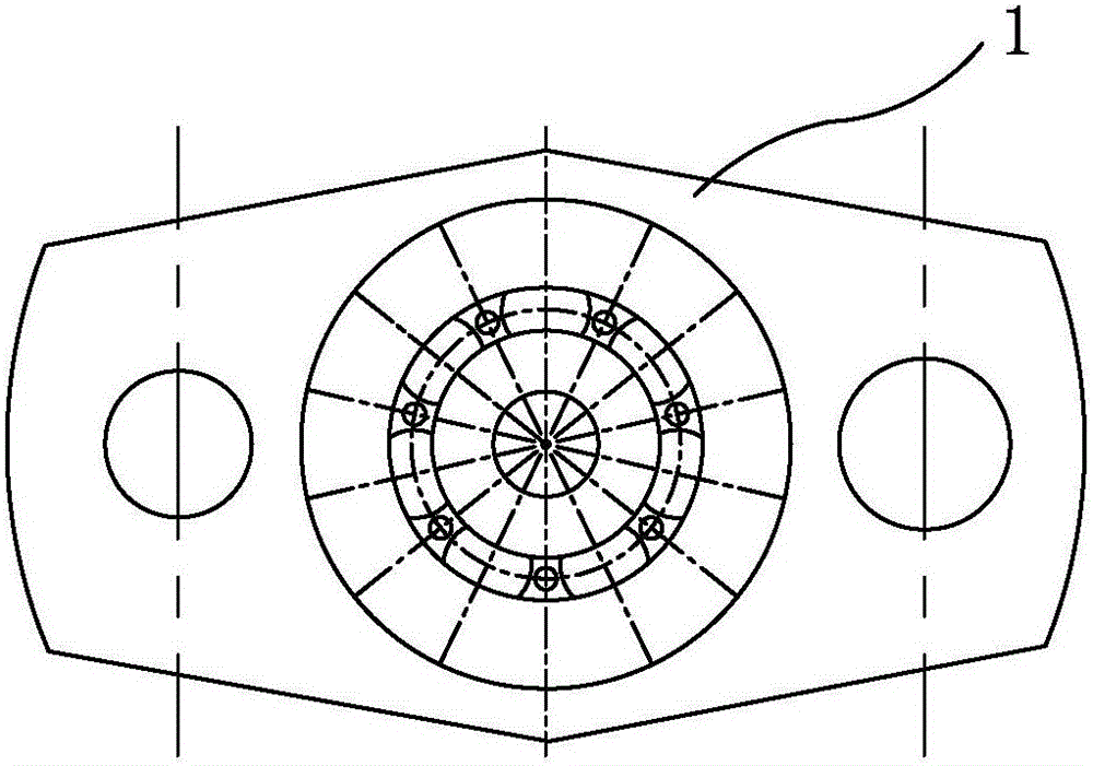
[0021] Combined with the above drawings, the name and serial number of the small bearing rivet cage decomposition mold parts of the present invention are: lower mold 1, upper mold 2, left guide post 3, sleeve removal mold assembly 4, end cover 5, countersunk head screw 6, guide Pin 7, right guide post 8, spring 9, nail removal pin 10, limit bushing 11, small bearing 12.

[0022] Such as Figure 1 to Figure 7 As shown, the implementation mode takes the small bearing rivet cage decomposition method for small bearings as an example. The rivet and cage decomposition process of the bearing rivet cage is as follows: the small bearing to be removed is placed on the lower mold 1, and the upper mold 2 Put the upper spring 9 on, and then install and remove the sleeve die assembly 4 along the left guide post 3 and the right guide post 8 holes of the upper die, and then adjust the upper and lower dies, and the sleeve die assembly 4, so that they are placed in the punching machine for stam...


PUM


Abstract

The invention discloses a small bearing rivet retainer dismantlement die and a dismantlement method thereof. The die is characterized in that the shapes of an upper die body and a lower die body of the dismantlement are matched with the model of bearings, the shape of a retainer and small holes matched with sizes and the number of retainer rivets, so that the small holes in the upper die body enable pins to pass conveniently, and the small holes in the lower die body enable dismantled rivets to pass; a die dismantlement and sleeving assembly of the retainer dismantlement die is provided with a left guide column and a right guide column, the pins transmit force to an end cap by means of a pressure machine along the left guide column and the right guide column so as to be driven, and the pins apply force to the rivets so that the rivets can be dismantled out of the retainer and separated from the retainer. When impact force of a punching machine finishes one-shot rivet dismantlement, the die dismantlement and sleeving assembly resets under the action of spring force between the die dismantlement and sleeving assembly and the upper die body, and the dismantled rivets fall into a cavity, easy to clean, of the lower die body. A next bearing to be dismantled and conveyed into the cavity is received repeatedly, so that quality problems of inner rings and outer rings of unqualified bearings are conveniently detected, and the inner rings and the outer rings of the dismantled bearings are reused.

Description

technical field [0001] The invention relates to the field of bearings, and relates to a small-sized bearing rivet cage decomposition mold and a decomposition method thereof. Background technique [0002] Bearings are usually composed of four main components, namely inner sleeve, outer sleeve, rolling elements, and cage. The function of the cage is to keep the rolling elements in the correct position when the bearing is running. Once the bearing cage is damaged, it will usually cause the overall failure of the bearing. Sometimes the rolling elements will be crushed due to the breakage of the cage, and even the bearing will be locked to cause an accident. It can be seen that the role of the cage in the bearing cannot be ignored. As the rivet connecting the cage, it is the guarantee for the reliable operation of the cage. If it breaks, it will cause damage to the cage. [0003] The speed of ball bearings for general purposes is relatively low, and cage fracture is relatively...

Claims


Application Information

Patent Timeline
Patent Type & Authority Patents(China)
IPC IPC(8): B25B27/02
CPCB25B27/02
Inventor 李芝根楼志伟
Owner NINGBO DAER MACHINERY TECH CO LTD
Why Eureka
Try Eureka