Ammonia decomposition catalysts and their production processes, as well as ammonia treatment method

a technology of ammonia decomposition catalyst and ammonia treatment method, which is applied in the direction of catalyst activation/preparation, metal/metal-oxide/metal-hydroxide catalyst, etc., can solve the problems of low ammonia decomposition rate, unfavorable method, and nox production, and achieves simple and easy manner

Inactive Publication Date: 2011-07-21
NIPPON SHOKUBAI CO LTD
View PDF6 Cites 35 Cited by
  • Summary
  • Abstract
  • Description
  • Claims
  • Application Information

AI Technical Summary

Benefits of technology

[0032]According to the present invention, there are provided a catalyst capable of efficiently decomposing ammonia, in a wide ammonia concentration range from low concentration to high concentration, into nitrogen and hydrogen at relatively low temperatures and at high space velocities to obtain high-purity hydrogen without using a noble metal; a process for producing the catalyst in a simple and easy manner; and a method of decomposing ammonia into nitrogen and hydrogen to obtain hydrogen, using the catalyst.

Problems solved by technology

This ammonia treatment method, however, often produces NOx as a by-product, and therefore newly requires an NOx treatment facility.
Thus, the method is unfavorable.
This ammonia treatment method, however, has a low ammonia decomposition rate, and therefore is not practicable.
Thus, the method has a major problem in view of cost, and therefore is not practicable.
To obtain high-purity hydrogen using conventionally proposed ammonia decomposition catalysts, very high reaction temperatures are required, or numerous costly catalysts need to be used.
As described above, all the conventional ammonia decomposition catalysts cannot efficiently decompose ammonia at relatively low temperatures and at high space velocities to obtain high-purity hydrogen.

Method used


Image

  • Ammonia decomposition catalysts and their production processes, as well as ammonia treatment method
  • Ammonia decomposition catalysts and their production processes, as well as ammonia treatment method
  • Ammonia decomposition catalysts and their production processes, as well as ammonia treatment method

Examples


examples

[0140]The present invention will be explained below more specifically by reference to Experimental Examples, but the present invention is not limited to these Experimental Examples. The present invention can be put into practice after appropriate modifications or variations within a range meeting both of the gist described above and below, all of which are included in the technical scope of the present invention.

[0141]—Ammonia Decomposition Catalyst (I)—

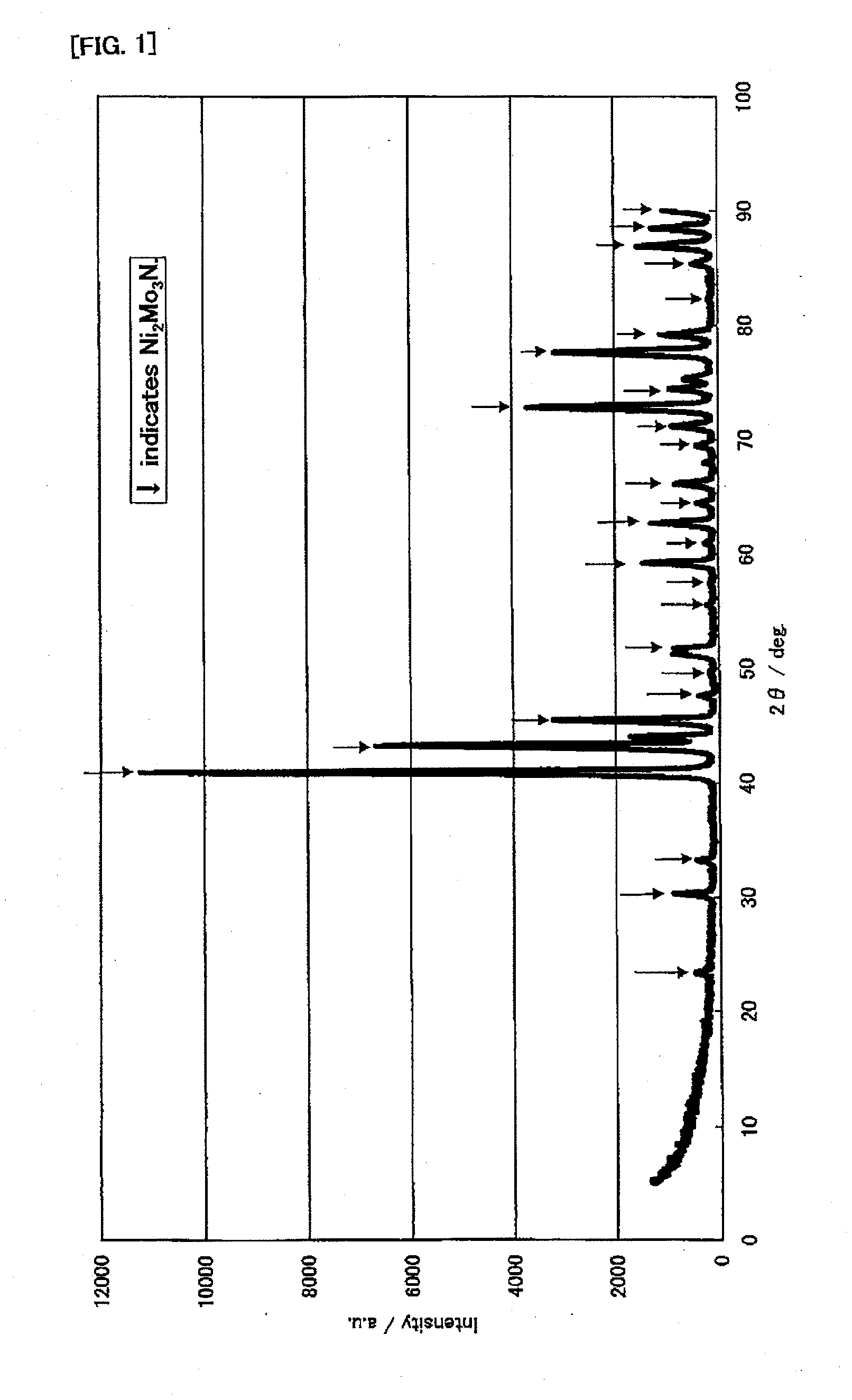
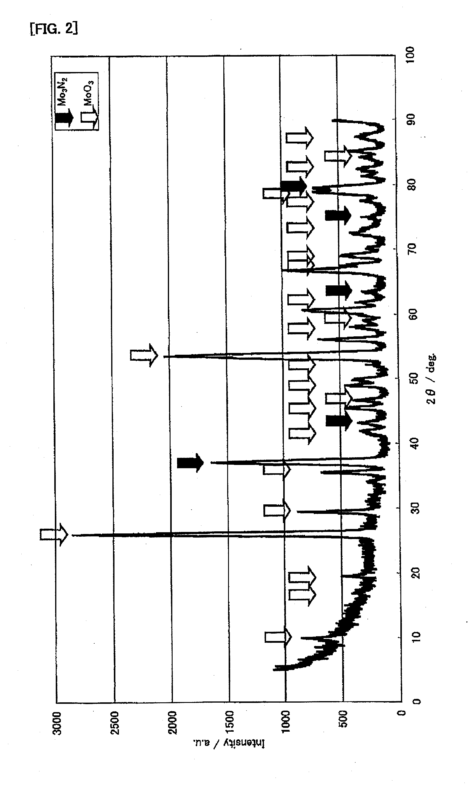
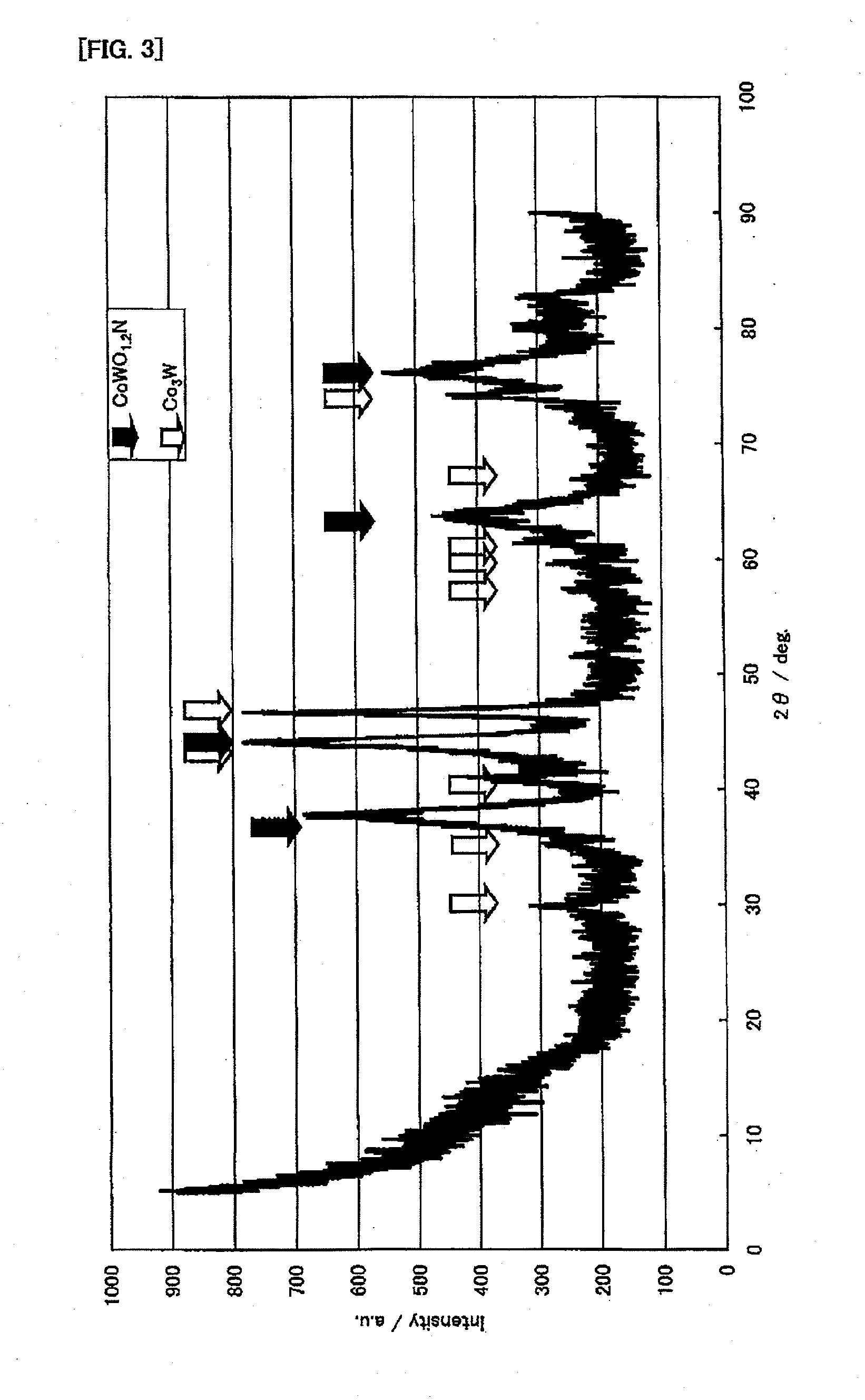
[0142]First, the following will explain production examples and performance evaluations of the ammonia decomposition catalyst (I). In this connection, for X-ray diffraction measurements, an X-ray diffractometer (product name “RINT-2400” available from Rigaku Corporation) was used. The X-ray diffraction measurements were made, using CuKα (0.154 nm) for an X-ray source, under the measurement conditions: the X-ray output was 50 kV and 300 mA; the divergence slit was 1.0 mm; the divergence vertical limit slit was 10 mm; the scanning spee...

experimental example i-1

[0143]First, 80.00 g of cobalt nitrate hexahydrate was dissolved in 400.00 g of distilled water. Separately, 48.53 g of ammonium molybdate was gradually added to and dissolved in 250 g of boiled distilled water. After both aqueous solutions were mixed together, the mixture was heated and agitated, and was evaporated to dryness. The obtained solid product was dried at 120° C. for 10 hours, was then baked at 350° C. in a stream of nitrogen for 5 hours, and was baked at 500° C. in a stream of air for 3 hours. It was confirmed by the X-ray diffraction measurements that α-CoMoO4 was obtained.

[0144]Further, a reaction tube made of SUS316 was filled with from 0.5 to 1.0 mL of α-CoMoO4, and the temperature was increased to 400° C. while from 30 to 50 mL / min of a nitrogen gas (hereinafter abbreviated as “nitrogen”) was allowed to flow. Then, an ammonia decomposition catalyst (hereinafter referred to as “CoMoO4”) was obtained by carrying out the treatment of increasing the temperature to 700°...

experimental example i-2

[0145]First, 80.00 g of cobalt nitrate hexahydrate was dissolved in 400.00 g of distilled water. Separately, 48.53 g of ammonium molybdate was gradually added to and dissolved in 250 g of boiled distilled water. After both aqueous solutions were mixed together, the mixture was heated and agitated, and was evaporated to dryness. The obtained solid product was dried at 120° C. for 10 hours, was then baked at 350° C. in a stream of nitrogen for 5 hours, and was baked at 500° C. in a stream of air for 3 hours. It was confirmed by the X-ray diffraction measurements that α-CoMoO4 was obtained.

[0146]Then, 0.089 g of cesium nitrate was dissolved in 3.23 g of distilled water. The resulting aqueous solution was uniformly penetrated into 6.00 g of α-CoMoO4 in a dripping manner, and the resulting product was dried at 90° C. for 10 hours. Then, it was confirmed by the X-ray diffraction measurements that α-CoMoO4 was obtained.

[0147]Further, a reaction tube made of SUS316 was filled with from 0.5 ...


PUM

PropertyMeasurementUnit
temperatureaaaaaaaaaa
temperaturesaaaaaaaaaa
temperatureaaaaaaaaaa

Abstract

The ammonia decomposition catalyst of the present invention is a catalyst for decomposing ammonia into nitrogen and hydrogen, including a catalytically active component containing at least one kind of transition metal selected from the group consisting of molybdenum, tungsten, vanadium, chromium, manganese, iron, cobalt, and nickel, preferably including: (I) a catalytically active component containing: at least one kind selected from the group consisting of molybdenum, tungsten, and vanadium; (II) a catalytically active component containing a nitride of at least one kind of transition metal selected from the group consisting of molybdenum, tungsten, vanadium, chromium, manganese, iron, cobalt, and nickel; or (III) a catalytically active component containing at least one kind of iron group metal selected from the group consisting of iron, cobalt, and nickel, and at least one metal oxide, thereby making it possible to effectively decompose ammonia into nitrogen and hydrogen at relatively low temperatures and at high space velocities to obtain high-pure hydrogen.

Description

TECHNICAL FIELD[0001]The present invention relates to catalysts for decomposing ammonia into nitrogen and hydrogen, ant their production processes, as well as an ammonia treatment method using each of the catalysts.BACKGROUND ART[0002]Ammonia has an odor, particularly an irritating malodor, and therefore, if ammonia at or above an odor threshold is contained in a gas, the ammonia needs to be treated. In response, conventionally, various ammonia treatment methods have been studied. For example, proposals have been made for a method of bringing ammonia into contact with oxygen to oxidize the ammonia into nitrogen and water; and a method of decomposing ammonia into nitrogen and hydrogen.[0003]For example, Patent Document 1 discloses an ammonia treatment method of using, for example, a platinum-alumina catalyst, a manganese-alumina catalyst, or a cobalt-alumina catalyst, in order to oxidize ammonia produced in a coke oven into nitrogen and water, and using, for example, an iron-alumina ...

Claims


Application Information

Patent Timeline
Patent Type & Authority Applications(United States)
IPC IPC(8): C01B3/04B01J23/882B01J23/883B01J23/34B01J23/881B01J23/888B01J23/847B01J23/887B01J37/08C01B21/06B01J27/24B01J23/76B01J23/83B01J21/06B01J21/04B01J21/10B01J37/16C22C38/00C22C27/04C22C27/02C22C27/06C22C22/00C22C19/07C22C19/03
CPCB01D53/8634B01D2255/202Y02E60/364B01D2255/20707B01D2255/20753B01D2257/406B01J23/002B01J23/28B01J23/34B01J23/74B01J23/75B01J23/755B01J23/78B01J23/83B01J23/88B01J23/8872B01J23/888B01J27/053B01J27/24B01J37/0236B01J2523/00B01J2523/3712B01J2523/48B01J2523/845B01J2523/842B01J2523/27B01J2523/31B01J2523/69B01J2523/847B01J2523/13B01J2523/25B01J2523/24B01J2523/3706B01J2523/15B01J2523/68B01J2523/36B01J2523/22Y02E60/36B01J23/889C01B21/02C01B3/04
Inventor OKAMURA, JUNJIKIRISHIKI, MASARUYOSHIMUNE, MASANORITSUNEKI, HIDEAKI
Owner NIPPON SHOKUBAI CO LTD
Why Eureka
Try Eureka