

Gas treating device
a gas treatment device and gas treatment technology, applied in the direction of energy-based chemical/physical/physical-chemical processes, chemical/physical/physical-chemical processes, chemistry apparatus and processes, etc., can solve the problems of decomposition of unpleasant odorous components in the air, reduce and reduce the size of the gas treatment device. , to achieve the effect of enhancing the processing capability of the gas treatment device, reducing the space required for installation
- Summary
- Abstract
- Description
- Claims
- Application Information
AI Technical Summary
Benefits of technology
Problems solved by technology
Method used
Image

Examples
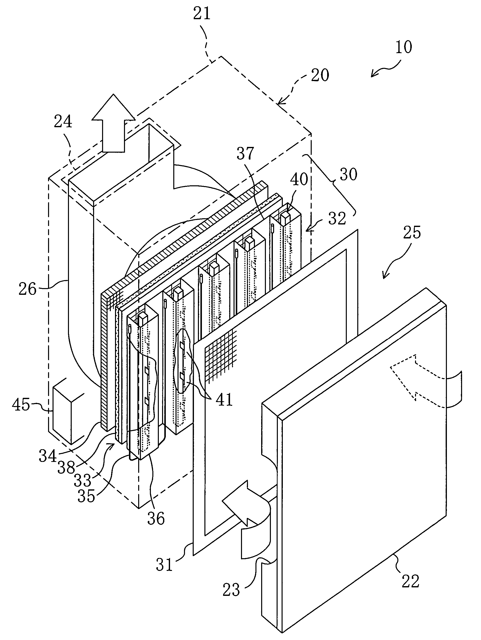
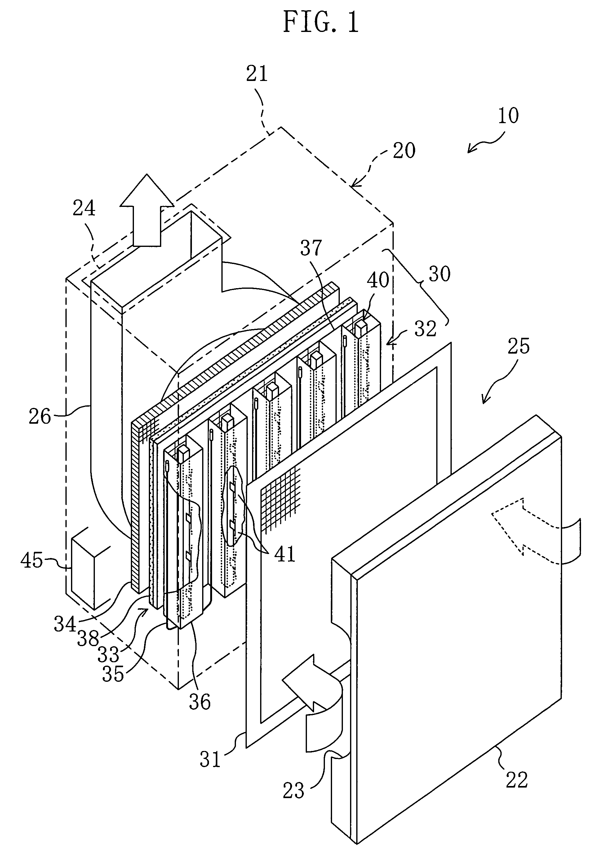
first embodiment
Variations of First Embodiment
[0082]With respect to the air purifying device (10) of the first embodiment, the change in configuration of the plasma generating device (40) in the ionization part (32) may be made.
[0083]In a first variation of the first embodiment (FIG. 3), the discharge electrode (41) is attached to the electrode holding member (43) of the plasma generating device (40).
[0084]The discharge electrode (41) is a small piece shaped like a triangular plate and is provided such that it stands on a side surface of the electrode holding member (43) on the front surface portion's (37a) side. And, upon application of voltage, streamer discharges are generated towards the counter electrode (36) from the leading end of the discharge electrode (41).
[0085]In a second variation of the first embodiment (FIG. 4), the electrode holding member (43) of the plasma generating device (40) comprises a portion which serves as the discharge electrode (41). In other words, the discharge electro...
second embodiment
of the Invention
[0088]A second embodiment of the present invention is similar to the first embodiment, with the exception of modifications in the configuration of the ionization part (32). The difference between the first embodiment and the present embodiment is described below.
[0089]With reference to FIG. 5, in the air purifying device (10) of the present embodiment, the front surface portion (37a) of the ionization part (32) is provided with a plurality of circular vent holes (51). Each vent hole (51) is formed, such that its opening lies at the approximately same level as that of the intermediate point between adjoining securing members (44) mounted on the electrode holding member (43). A part of the room air after passage through the pre-filter (31) flows, through the vent holes (51), into the ionization part (32), as indicated by solid line of FIG. 5.
[0090]Meanwhile, in the plasma generating device (40), a plasma of low temperature is being generated by streamer discharge betwe...
third embodiment
of the Invention
[0091]A third embodiment of the present invention is similar to the first embodiment, with the exception of modifications in the configuration of the ionization part (32). With reference to FIG. 6, the difference between the first embodiment and the present embodiment is described below. FIG. 6(A) is a top plan view. FIG. 6(B) is an illustration as viewed from upstream of the airflow. FIG. 7(A) is a top plan view. FIG. 7(B) is an illustration as viewed from upstream of the airflow.
[0092]In the air purifying device (10) of the present embodiment, the back surface portion (37c) of the ionization part (32) is provided with a plurality of insulators (60) for insulation. The insulators (60) are used to insulate electrical continuity and are evenly spaced apart from each other in the vertical direction of the negative electrode member (37). Attached to a side surface of each insulator (60) on the pre-filter's (31) side is a conducting member (61). The conducting member (61...
PUM
 Abstract
Description
Claims
Application Information