Rotary compressor

A rotary compressor and compressor technology, applied in the field of compressors, can solve the problems of reducing compressor life and increasing wear, and achieve the effect of reducing oil output

Inactive Publication Date: 2011-03-23
LG ELECTRONICS (TIANJIN) APPLIANCES CO LTD
View PDF0 Cites 2 Cited by
  • Summary
  • Abstract
  • Description
  • Claims
  • Application Information

AI Technical Summary

Problems solved by technology

[0008] In the upper part of the compressor, when the gaseous refrigerant is discharged through the exhaust pipe, the oil mist of the lubricating oil will be c

Method used


Image

  • Rotary compressor
  • Rotary compressor
  • Rotary compressor

Examples


Embodiment Construction

[0018] The structure of the rotary compressor of the present invention will be described in detail below with reference to the accompanying drawings.

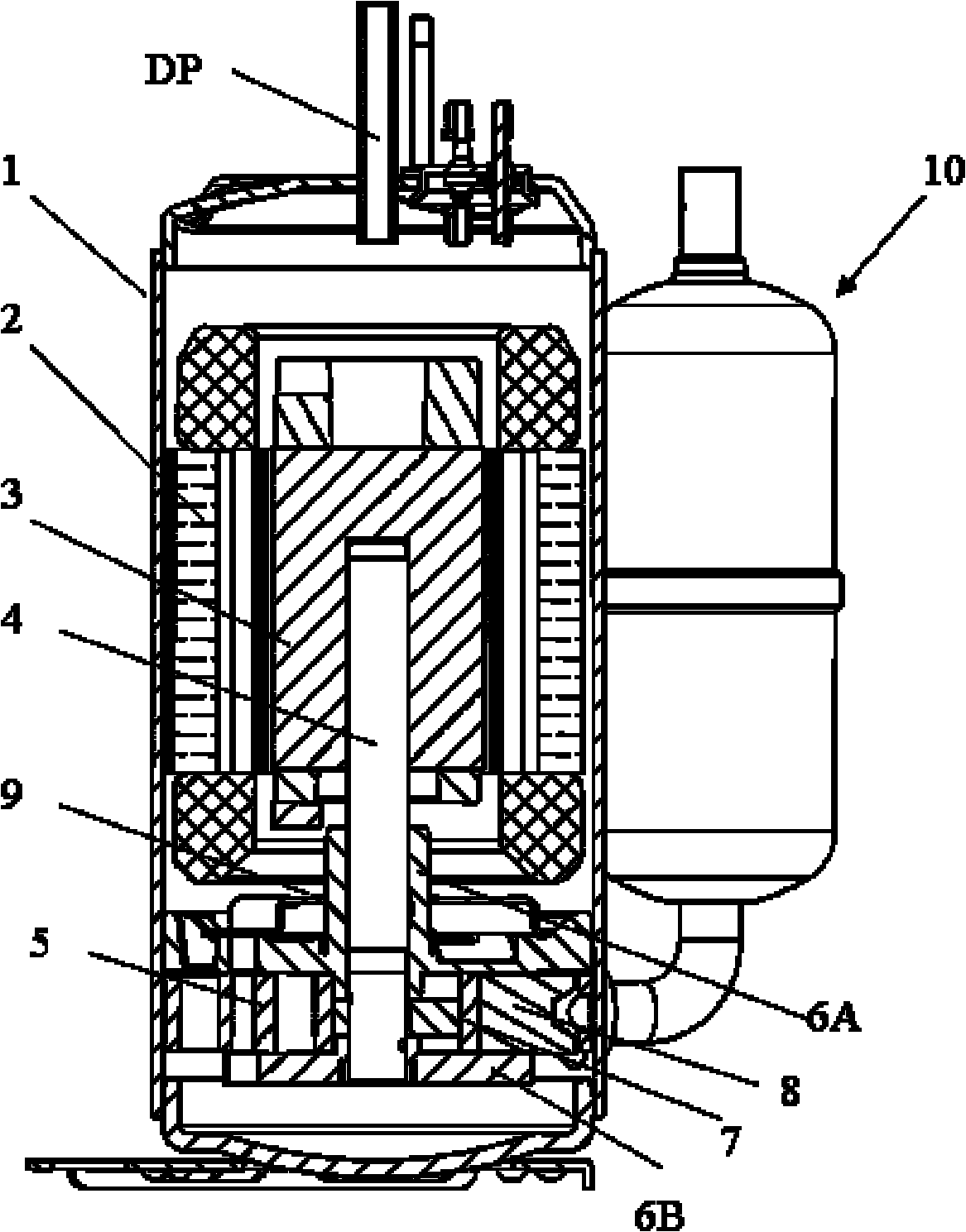
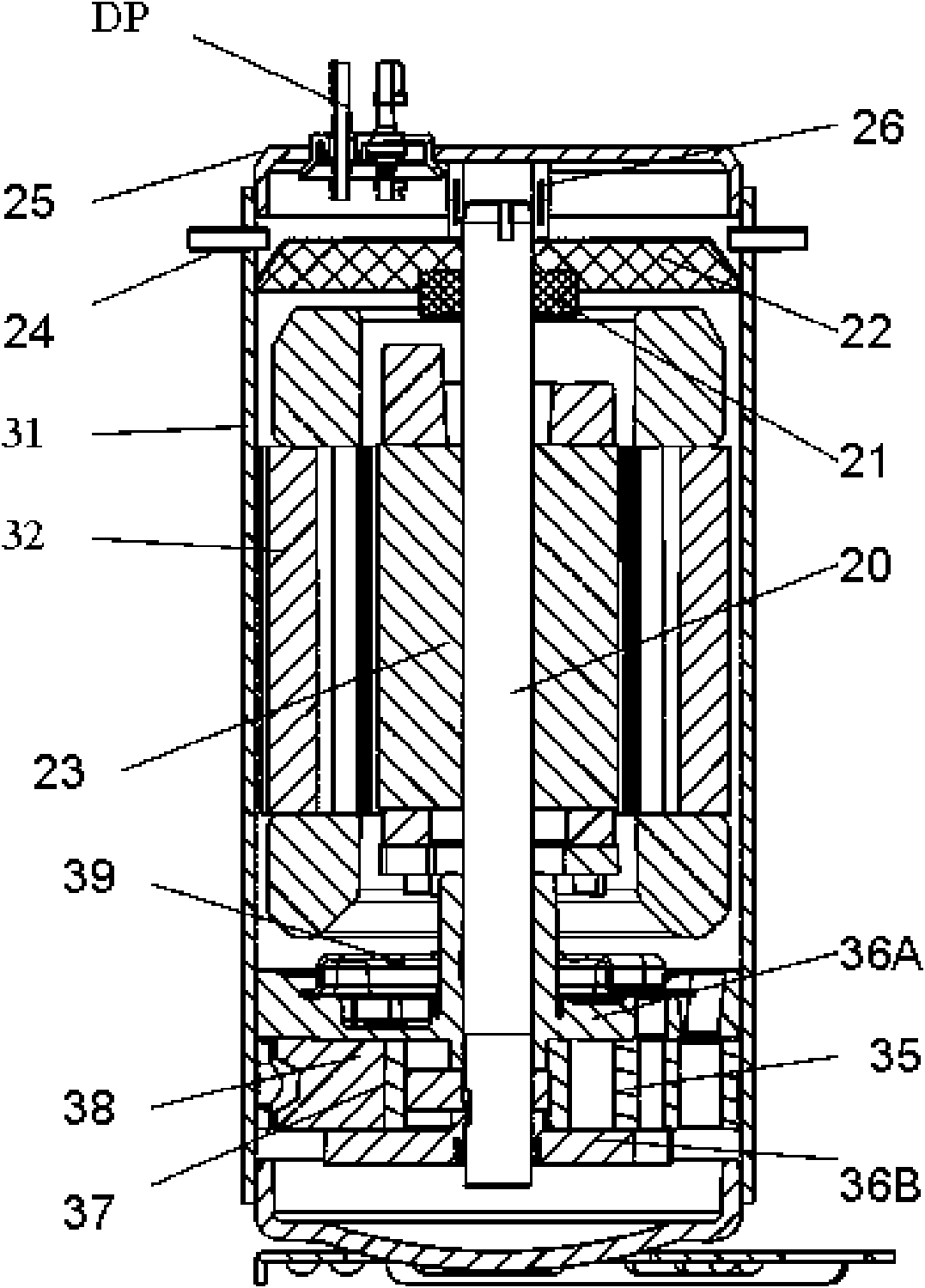
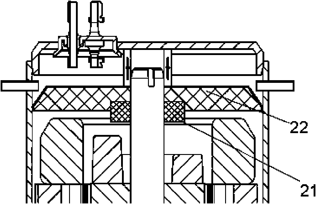
[0019] Such as figure 2 and image 3 As shown, the rotary compressor of the present invention includes: a housing 31 , a compressor crankshaft 20 disposed in the housing 31 and having an eccentric portion, a mechanical structure, a motor drive and a compressor structure. Wherein, the motor driving part includes: a motor stator 32 and a motor rotor 23 arranged inside the housing 31, and the center of the motor rotor 23 is press-fitted and installed on the crankshaft 20; the compression structure part includes: The circular cylinder 35 fixedly arranged on the inner peripheral surface of the housing 31, the roller ring 37 which is arranged on the eccentric part of the crankshaft 34 and rotates eccentrically in the cylinder 35 under the action of the crankshaft 34, and one end which is crimped on the roller ring 37 On the outer ...


PUM


Abstract

The invention discloses a rotary compressor, which comprises a crankshaft of the compressor, a compressing structure part, an upper bearing, a lower bearing and a motor driving part, wherein the crankshaft of the compressor is arranged in a casing and is provided with an eccentric part, the compressing structure part is used for compressing coolant gas, the upper bearing and the lower bearing are respectively arranged at the upper side and the lower side of the compressing structure part, the motor driving part is used for driving the compressing structure part, the upper part of the casing is provided with an upper cover, the crankshaft upwards extends, the upper end of the crankshaft is arranged in a bearing arranged under the upper cover, a cylindrical gas-liquid separator is arranged on the crankshaft arranged between the bearing and a rotor, the diameter of the gas-liquid separator is smaller than that of the rotor, at least one exhaust opening is arranged on the outer peripheral surface of the upper part of the casing, and a filter screen is arranged between the exhaust opening and the gas-liquid separator. The rotary compressor of the invention separates small oil drops carried in gaseous coolants through the gas-liquid separator and the filter screen, and reduces the oil outlet quantity of the compressor.

Description

technical field [0001] The present invention relates to compressors, in particular to a rotary compressor. Background technique [0002] Rotary compressors usually eccentrically combine the roller ring of the compression structure part on the crankshaft combined with the motor drive part, and the roller ring rotates in the compression space of the circular cylinder to suck, compress and discharge the refrigerant. [0003] The structure of the existing rotary compressor is generally as follows figure 1 As shown, it includes: a housing 1, a crankshaft 4 of the compressor with an eccentric part arranged in the housing 1, a mechanical structure part, a motor drive part and a compressor structural part. Wherein, the motor driving part includes: a motor stator 2 and a motor rotor 3 arranged inside the housing 1, and the center of the motor rotor 3 is press-fitted and installed on the crankshaft 4; the compression structure part includes: The circular cylinder 5 fixedly arranged ...

Claims


Application Information

Patent Timeline
IPC IPC(8): F04C18/344F04C29/02
Inventor 许崇文
Owner LG ELECTRONICS (TIANJIN) APPLIANCES CO LTD
Why Eureka
Try Eureka