Oil supply device

An oil supply device and oil supply technology, applied in the direction of power unit, control device, transmission control, etc., to achieve the effect of improving energy efficiency and suppressing large-scale

Active Publication Date: 2017-12-01
AISIN AW CO LTD
View PDF5 Cites 0 Cited by
  • Summary
  • Abstract
  • Description
  • Claims
  • Application Information

AI Technical Summary

Problems solved by technology

In this regard, the technique of Patent Document 1 has room for improvement

Method used


Image

  • Oil supply device
  • Oil supply device
  • Oil supply device

Examples


no. 1 approach

[0043] refer to Figure 1 ~ Figure 4 , the first embodiment of the oil supply device of the present invention will be described.

[0044] 1-1. The overall structure of the vehicle drive unit

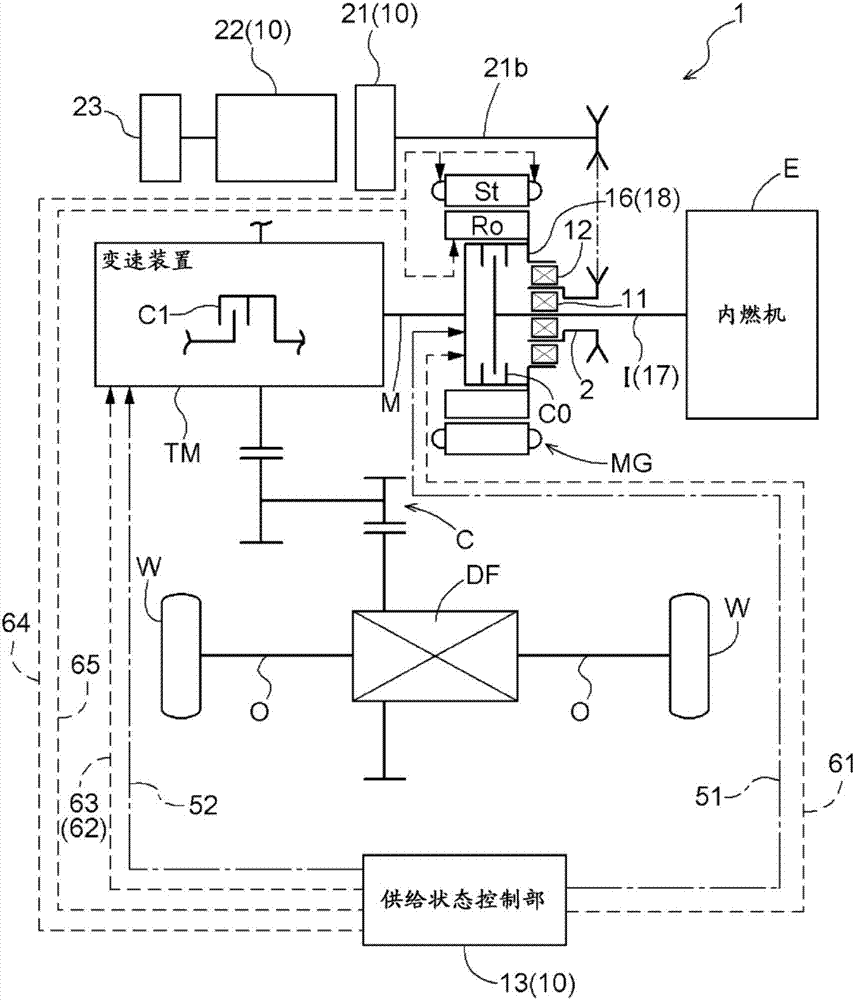
[0045] First, the structure of the vehicle drive device 1 which is the fuel supply target of the fuel supply device 10 according to the present embodiment will be described. like figure 1 As shown, the vehicle driving device 1 of the present embodiment includes an input shaft I drivingly connected to the internal combustion engine E, an output shaft O drivingly connected to the wheels W, an engagement device C0 for disengagement, a rotary electric machine MG for driving the wheels, and a transmission device TM. , gear mechanism C and differential gear device DF. The disengagement engagement device C0, the rotary electric machine MG, the transmission device TM, the gear mechanism C, and the differential gear unit DF are provided on a transmission path connecting the input shaft I and t...

no. 2 approach

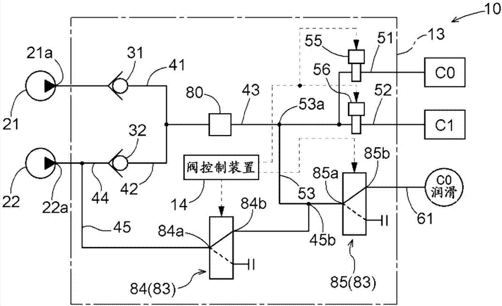
[0089] refer to Figure 5 A second embodiment of the oil supply device of the present invention will be described. In this embodiment, the point that the supply state control part 13 is equipped with the lubrication branch oil passage 53 is different from the said 1st Embodiment. Hereinafter, differences from the above-mentioned first embodiment will be mainly described, and points not particularly indicated are the same as those of the above-mentioned first embodiment.

[0090] like Figure 5As shown, in the present embodiment, the branch oil passage 45 is connected to the first lubricating oil passage 61 without passing through the oil passage downstream of the second check valve 32 (for example, the confluence oil passage 43 ). Furthermore, in the present embodiment, the communication state control valve 83 performs control to switch between a state in which the branch oil passage 45 communicates with the first lubricating oil passage 61 and a state in which the branch oi...

no. 3 approach

[0094] refer to Image 6 A third embodiment of the oil supply device of the present invention will be described. In the above-mentioned first and second embodiments, basically only the disengagement engagement device C0 is assumed to be in the slip engagement state, but in this embodiment, the vehicle drive device 1 can be configured to disengage the disengagement engagement device C0 according to the situation. One or both of the device C0 and the transmission engagement device C1 are controlled to be in a slip engagement state and transmit the rotation of the input shaft I to the output shaft O. Therefore, the lubricating device 10 of the present embodiment can be configured to supply a sufficient amount of lubricating oil to both the disengagement engagement device C0 and the transmission engagement device C1 . In addition, in the first embodiment described above, the branch oil passage 45 is configured to be connected to the first lubricating oil passage 61 via the lubric...


PUM


Abstract

There is desired an oil supply device that can supply an appropriate amount of oil to a vehicle drive device, while suppressing an increase in size of a hydraulic pump, in the case where torque of an internal combustion engine is transferred to wheels with an engagement device controlled to a slipping engagement state. An oil supply device (10) is provided with: a first hydraulic pump (21); a second hydraulic pump (22) driven by a dedicated drive-power source (23); a lubricating oil passage (61) for lubricating engagement devices (C0, C1); a first engagement oil passage (51) for controlling an engagement state of a release engagement device (C0); and a second engagement oil passage (52) for controlling an engagement state of a gear-shift engagement device (C1). In cases when the engagement devices are controlled so as to be in a slip engagement state, a supply state controller sets a state in which oil discharged from the first hydraulic pump is supplied to the first engagement oil passage and the second engagement oil passage, and oil discharged from the second hydraulic pump is supplied to the lubricating oil passage.

Description

[0001] This application is a divisional application of the application number 201480010637.7 (international application number PCT / JP2014 / 059333), the application date is March 28, 2014, and the invention title is "oil supply device" technical field [0002] The present invention relates to an oil supply device for supplying oil to a driving device for a vehicle. The driving device for a vehicle comprises: an input member drivingly connected to an internal combustion engine; a rotating electric machine for driving a wheel; an output member connected to drive the wheel; and at least transmission means for shifting the rotation of the input member and transmitting it to the output member; and disengaging engagement means for disengaging the input member from the transmission. Background technique [0003] In the above-mentioned drive device for a vehicle, when performing an electric driving mode in which the vehicle is driven only by the torque of the rotary electric machine, t...

Claims


Application Information

Patent Timeline
Patent Type & Authority Applications(China)
IPC IPC(8): B60K6/48B60K6/547B60L1/00B60L11/14B60L15/20F16H61/00B60L50/16
CPCB60L50/16B60K6/48B60K6/547B60L1/003B60L15/2054F16H61/0031B60L2240/443F16H2061/0037B60W10/30B60W20/00Y02T10/72Y10S903/917Y02T10/62Y02T10/64Y02T10/7072Y02T10/70B60K6/543B60K6/54B60R17/02
Inventor 石川智己榎本和人野田和幸西尾聪铃木启司
Owner AISIN AW CO LTD
Why Eureka
Try Eureka