Rotary compressor and refrigeration cycle device having same

A technology of rotary compressor and compression mechanism, which is applied to rotary piston machinery, components of pumping devices for elastic fluids, and rotary piston/oscillating piston pump components, etc., which can solve the problem of oil drop in the compressor and other problems to achieve the effect of reducing oil discharge, sealing oil and temperature

Active Publication Date: 2019-01-04
GUANGDONG MEIZHI COMPRESSOR +1
View PDF6 Cites 0 Cited by
  • Summary
  • Abstract
  • Description
  • Claims
  • Application Information

AI Technical Summary

Problems solved by technology

However, when using the centrifugal oil supply pump of a rotary compressor installed in an air conditioner, etc., a large amount of oil discharge occurs in various operation modes such as low outside temperature start, defrost operation, and high-speed operation, resulting in a large amount of oil in the compressor. (Oil level) drop problem, insufficient oil supply pump will become the main cause of compressor failure

Method used


Image

  • Rotary compressor and refrigeration cycle device having same
  • Rotary compressor and refrigeration cycle device having same
  • Rotary compressor and refrigeration cycle device having same

Examples


Embodiment 1

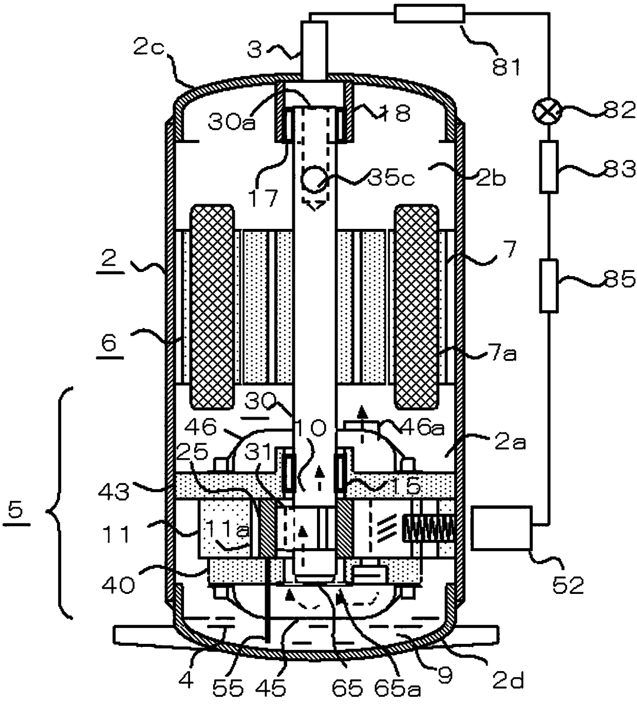
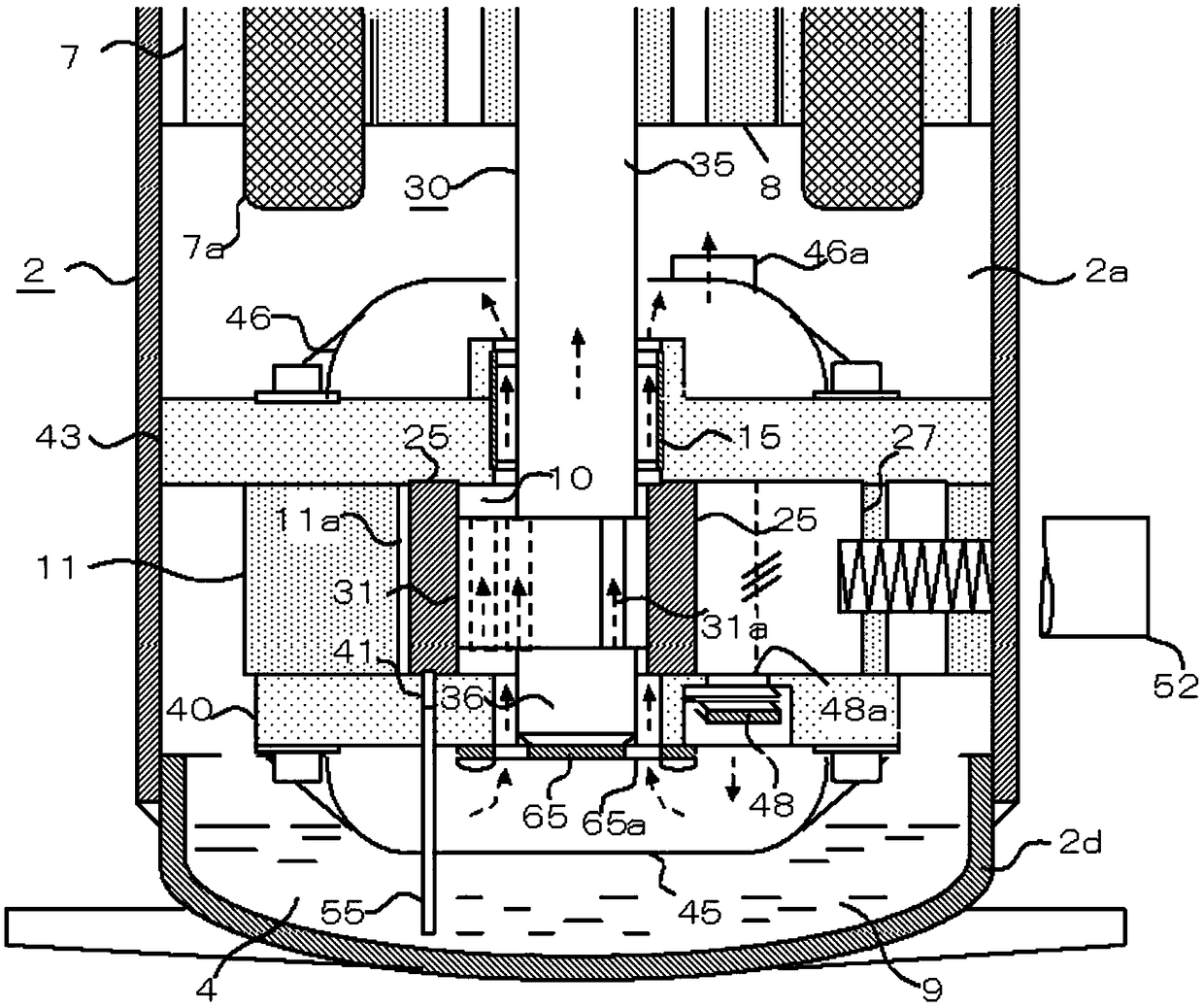
[0055] figure 1 It is an overall diagram of a single-cylinder rotary compressor and a diagram of a refrigeration cycle connected with the rotary compressor. figure 2 It is a detailed view of the compression mechanism part 5. figure 1 Among them, the outer peripheral wall of the stator 7 constituting the electric motor 4 (hereinafter referred to as the motor 4 ) and the outer peripheral wall of the second end plate 43 of the compression mechanism part 5 are fixed to the inner peripheral wall of the housing 2 .

[0056] The housing 2 is composed of a cylindrical housing, an upper housing end plate 2c and a lower housing end plate 2d welded at the upper and lower ends, and lubricating oil 9 (hereinafter referred to as oil 9 ) is injected into the oil storage tank 4 at the bottom of the housing 2 . The amount of sealed oil is much less than that of conventional rotary compressors.

[0057] The first compression chamber 11 a of the first cylinder 11 of the compression mechanism ...

Embodiment 2

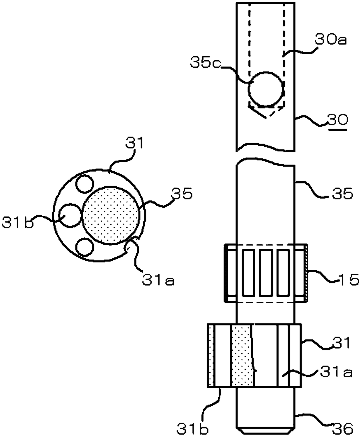
[0087] Figure 5 It is an overall sectional view of a two-cylinder rotary compressor and a diagram of a refrigeration cycle connected to the rotary compressor. Figure 6 It is a detailed view of the compression mechanism unit 5 . Figure 5 Among them, the intermediate partition plate 50 is fixed on the inner peripheral wall of the housing 2 , and the first rolling bearing 15 is arranged in the intermediate partition plate 50 . The second rolling bearing 17 is disposed on the bearing bracket 18 fixed at the center of the bearing frame 19 .

[0088] The crankshaft 30 includes, in addition to a main shaft 35 and a counter shaft 36 , a first eccentric shaft 31 , a second eccentric shaft 32 , and an intermediate shaft 33 connected to these eccentric shafts. Therefore, the intermediate shaft 33 of the crankshaft 30 is in sliding engagement with the first rolling bearing 15 and the upper end of the main shaft 35 and the second rolling bearing 17 . At the center of the crankshaft 3...


PUM


Abstract

The invention discloses a rotary compressor and a refrigeration circulating device with the same. An electric motor and a compressing mechanism part are contained in a sealed shell of the rotary compressor. The shell is provided with an air suction pipe, and lubricating oil is stored at the bottom of the shell. The compressing mechanism part comprises a cylinder, a piston, a slip sheet, a crankshaft, a first rolling bearing and an end plate. A compressing cavity is formed in the cylinder. The piston is arranged in the compressing cavity in an eccentric rotation mode. The slip sheet is arranged on the cylinder in a reciprocating motion mode. An eccentric shaft of the crankshaft is externally sleeved with the piston to drive the piston to rotate in an eccentric mode. The crankshaft is matched with the first rolling bearing. The end plate is arranged on the cylinder to support the crankshaft. Oil-containing refrigerant gas exhausted from the compressing cavity at least needs to lubricate the first rolling bearing. According to the rotary compressor, the oil discharge amount of the compressor is reduced, and the phenomenon that the liquid level of lubricating oil in an oil storage tank drops dramatically can be avoided.

Description

technical field [0001] The invention relates to the refrigeration field, in particular to a rotary compressor and a refrigeration cycle device having the same. Background technique [0002] All of the current rotary compressors use sliding bearings, and use a centrifugal oil supply pump that utilizes the rotation of the crankshaft. However, when using the centrifugal oil supply pump of a rotary compressor installed in an air conditioner, etc., a large amount of oil discharge occurs in various operation modes such as low outside temperature start, defrost operation, and high-speed operation, which may cause the oil in the compressor to (Oil level) drop problem, insufficient oil supply pump will become the main cause of compressor failure. Contents of the invention [0003] The present invention aims to solve one of the technical problems in the related art at least to a certain extent. [0004] For this reason, the present invention proposes a rotary compressor, which doe...

Claims


Application Information

Patent Timeline
Patent Type & Authority Patents(China)
IPC IPC(8): F04C23/02F04C18/356F04C29/02
CPCF04C18/3562F04C23/02F04C29/028F04C2240/50
Inventor 小津政雄宋鹏杰王玲
Owner GUANGDONG MEIZHI COMPRESSOR
Why Eureka
Try Eureka