Operating machine
A technology of working machinery and electric motors, which is applied in the field of working machinery and can solve problems such as deterioration
- Summary
- Abstract
- Description
- Claims
- Application Information
AI Technical Summary
Problems solved by technology
Method used
Image
Examples
Embodiment approach 1
[0056] "Implementation 1"
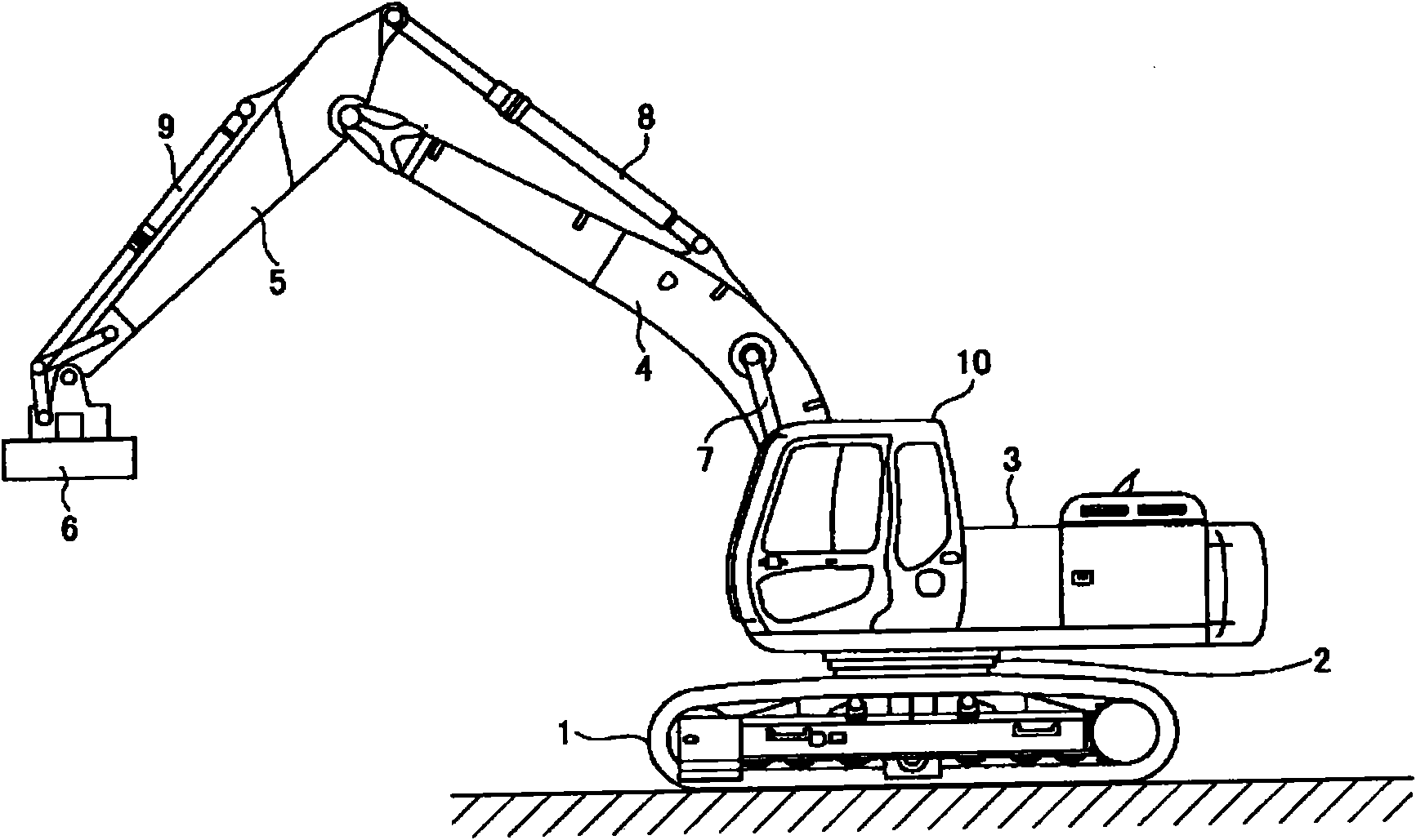
[0057] figure 1 It is a side view showing the hybrid construction machine according to the first embodiment.
[0058] On the undercarriage 1 of this hybrid construction machine, an upper revolving body 3 is mounted via a revolving mechanism 2 . In addition, in the upper slewing body 3, in addition to the boom 4, the boom 5, and the lifting magnet 6, and the boom cylinder 7, the boom cylinder 8, and the bucket cylinder 9 for hydraulically driving these, there are also mounted Cockpit 10 and power source are arranged.
[0059] "the whole frame"
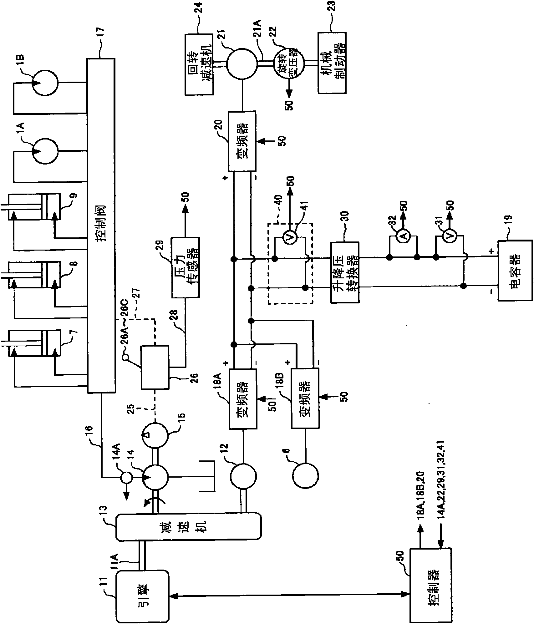
[0060] figure 2 It is a block diagram showing the configuration of the hybrid construction machine according to the first embodiment. in the figure 2 Among them, the mechanical power system is represented by a double line, the high-pressure hydraulic line is represented by a solid line, the pilot line is represented by a dotted line, and the electric drive or control system is represented by a dotted ...
Embodiment approach 2
[0146] "Implementation 2"
[0147] The hybrid type construction machine according to the second embodiment differs from the first embodiment in that the charge amount (SOC) of the capacitor 19 is set according to the rotation speed of the engine 11 . Therefore, an electrical signal indicating the rotational speed of the engine 11 is input to the controller 50 .
[0148]In Embodiment 2, the controller 50 monitors the engine speed transmitted from the control device (for example, ECU (Electronic Control Unit)) of the engine 11 .
[0149] In addition, here, for example, if the rotational speed of the engine 11 when idling is set to 1000 rpm and the maximum allowable rotational speed is set to 2000 rpm, the threshold for determination may be set to, for example, 1200 rpm.
[0150] Here, the rotational speed of the engine 11 is switched by a displacement switch disposed together with the operating device 26 in the cabin 10 . For example, if the rotational speed of the engine 11 w...
Embodiment approach 3
[0172] "Implementation Mode 3"
[0173] The hybrid construction machine according to Embodiment 3 is different from Embodiment 1 in that the capacitors are set according to the presence or absence of operation of levers 26A and 26B and pedal 26C (hereinafter, in Embodiment 3, abbreviated as "rod 26A, etc."). 19 SOC. Therefore, the controller 50 is configured to input an electrical signal indicating the presence or absence of operation of the lever 26A or the like transmitted from the pressure sensor 29 .
[0174] The hybrid construction machine according to the third embodiment determines the presence or absence of work based on the presence or absence of operation of the lever 26A or the like.
[0175] In addition, since other structures are based on the hybrid type construction machine of Embodiment 1, repeated description is omitted.
[0176] "Setting of charging capacity (SOC)"
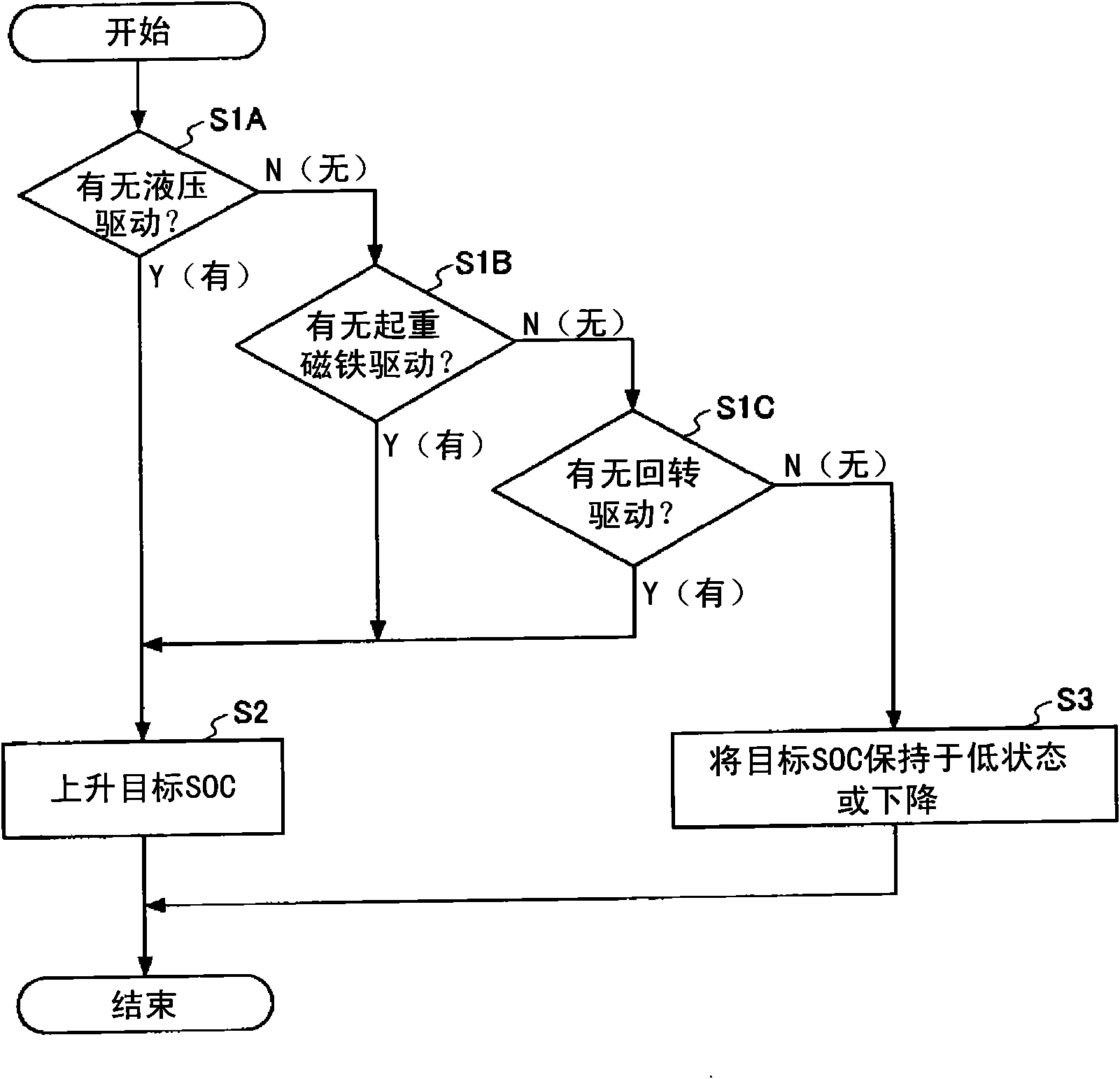
[0177] In the hybrid construction machine according to Embodiment 3, the charged capacity (...
PUM
 Abstract
Description
Claims
Application Information
 - R&D
- Intellectual Property
- Life Sciences
- Materials
- Tech Scout
- Unparalleled Data Quality
- Higher Quality Content
- 60% Fewer Hallucinations
Browse by: Latest US Patents, China's latest patents, Technical Efficacy Thesaurus, Application Domain, Technology Topic, Popular Technical Reports.
© 2025 PatSnap. All rights reserved.Legal|Privacy policy|Modern Slavery Act Transparency Statement|Sitemap|About US| Contact US: help@patsnap.com


