Eureka AIR delivers breakthrough ideas for toughest innovation challenges, trusted by R&D personnel around the world.

Large third-stage cyclone separator

A cyclone separator and cyclone technology, which is applied to cyclone devices, devices whose axial directions of cyclones can be reversed, etc., can solve the problems of increased thermal stress, increased expansion difference, increased gravity, etc. Differential radial expansion, lower thermal stress levels, longer life effects

Active Publication Date: 2011-03-30
CHINA PETROCHEMICAL CORP +1
View PDF3 Cites 0 Cited by
  • Summary
  • Abstract
  • Description
  • Claims
  • Application Information

AI Technical Summary

Problems solved by technology

[0005] In order to solve the large-scale process of the existing cyclone separator, due to the increase in the number of sub-cyclones, the increase in the gas collection chamber and the corresponding increase in expansion difference, increase in thermal stress, and deformation caused by increase in gravity and many other technologies Problem, the present invention provides a large-scale third-stage cyclone separator with a new structure

Method used


Image

  • Large third-stage cyclone separator
  • Large third-stage cyclone separator
  • Large third-stage cyclone separator

Examples


Embodiment 1

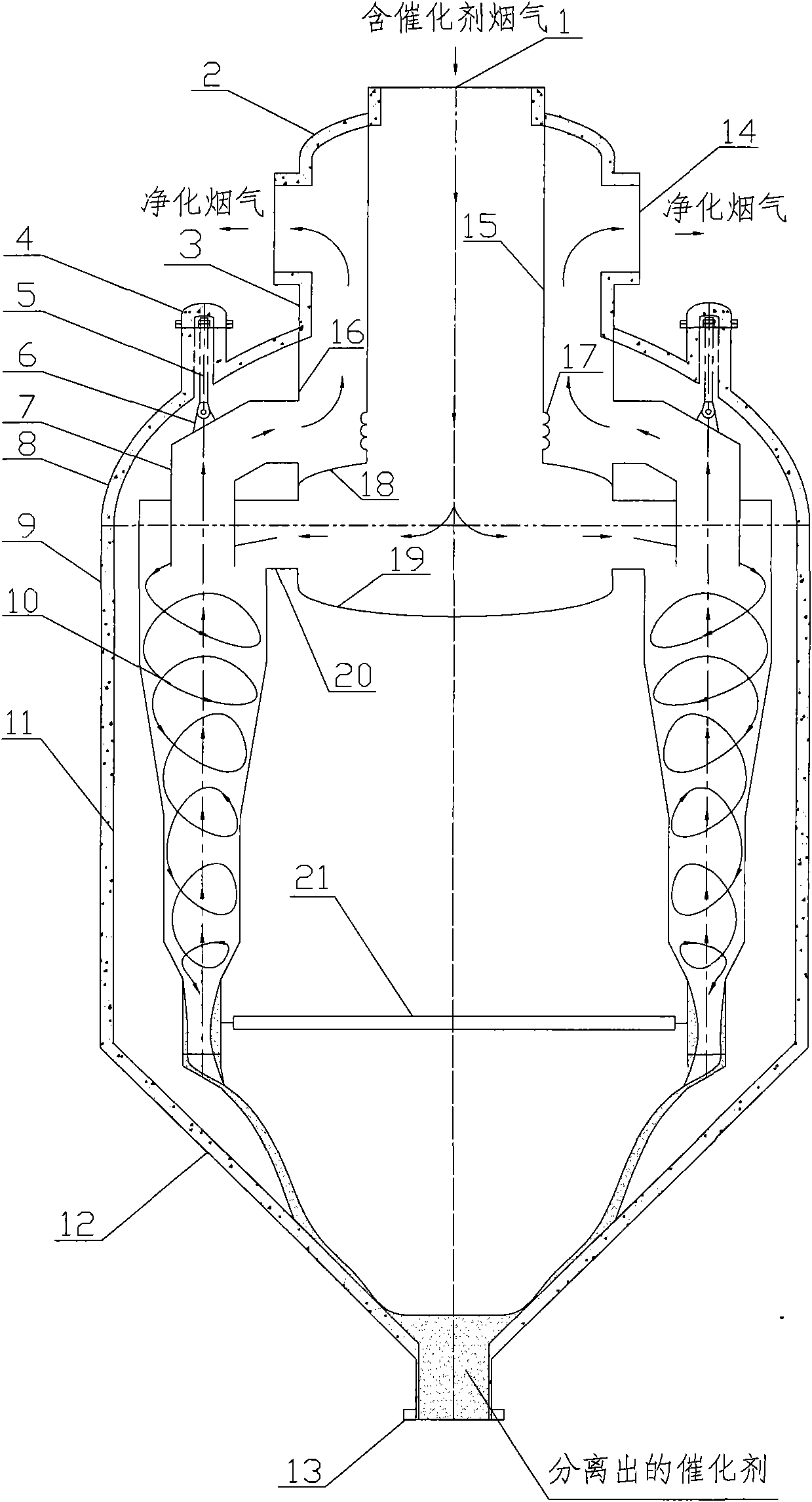
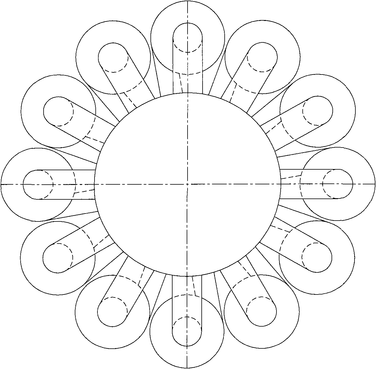
[0041] like figure 2 The large third stage cyclone shown has the following image 3 In the arrangement plane of the sub-cyclones shown, all the sub-cyclones are arranged on the same circumference.

Embodiment 2

[0043] like Figure 4 The very large third stage cyclone shown has the following Figure 5 In the arrangement plane of the sub-cyclones shown, all the sub-cyclones are arranged on two concentric circles. The sub-cyclones on two concentric circles are in Figure 4 The center is layered and staggered in the vertical direction. The cyclone inlet arranged in the inner ring can be perpendicular to the inner wall of the hot wall of the combined gas collection chamber of part 16, and can also be connected to the inner wall of the hot wall of the combined gas collection chamber of part 16 at a certain angle Figure 5 Only the case of connection at an angle is indicated by dashed lines.


PUM


Abstract

The invention relates to a large third-stage cyclone separator. The large third-stage cyclone separator comprises a fume inlet, a cyclone outlet, a cold-wall upper seal head, a cold-wall shell, a hot-wall sub-cyclone, an internal heat insulation layer, a clod-wall lower seal head, a catalyst outlet, a purified fume outlet and a hot-wall sub-cyclone inlet and is characterized in that: a convex combined type gas collection chamber is arranged at the upper part of the large third-stage cyclone separator, wherein the convex combined type gas collection chamber is a combined structure consisting of a convex gas collection chamber cold-wall seal head, a convex cold-wall air collection chamber, a fume inlet hot-wall inner tube, a combined type gas collection chamber hot-wall inner vessel wall, an expansion joint, a combined type air collection chamber hot-wall inner clapboard and a combined type gas collection chamber hot-wall seal head. The large third-stage cyclone separator is mainly used for performing gas-solid separation on high-temperature fume and a micro catalyst contained in the high-temperature fume in a catalytic cracking device for petroleum refining, various problems caused by a large inner gas collection chamber after equipment is upsized are solved, and the large third-stage cyclone separator is suitable for upsizing.

Description

technical field [0001] The invention belongs to petroleum refining and chemical equipment, and more specifically relates to a device for gas-solid separation of high-temperature flue gas and trace catalysts contained in a catalytic cracking unit of petroleum refining. Background technique [0002] There are two types of third-stage cyclone separators used in catalytic cracking units in the prior art: single-pipe type and internal sub-cyclone. [0003] U.S. Patent US7048782 and Chinese Patent ZL02245967.7 both disclose a single-pipe cyclone, which is essentially different from the present invention. [0004] Chinese patent ZL200820108124 discloses a third-stage cyclone separator that belongs to the same internal sub-cyclone as the present invention, see figure 1 . It can be seen from the figure that the sub-cyclone is directly connected to the bottom partition of the inner gas-collecting chamber through the air riser at the top, and is radially inside the gas-collecting cha...

Claims


Application Information

Patent Timeline
Patent Type & Authority Applications(China)
IPC IPC(8): B04C5/24B04C5/08B04C5/103
Inventor 程建民吴雷杨启业冯清晓张迎凯范声黄荣臻张荣克闫涛居颖彭科灵曹占飞李宇
Owner CHINA PETROCHEMICAL CORP
Why Eureka
Eureka Blog
Learn More