Drill stem friction welding valving movable punch

A friction welding and punching technology, which can be applied to cutting devices with nibbling action, shearing machine equipment, shearing devices, etc., and can solve problems such as low work efficiency

Inactive Publication Date: 2011-03-30
江阴兴鼎石油管具有限公司
View PDF0 Cites 0 Cited by
  • Summary
  • Abstract
  • Description
  • Claims
  • Application Information

AI Technical Summary

Problems solved by technology

It is obviously not feasible to use this method for the male joint. In the past, the turning method, or boring or drilling is used, and the work efficiency is very low. In the end, an unbroken ring that is difficult to remove is left in the drill pipe.

Method used


Image

  • Drill stem friction welding valving movable punch
  • Drill stem friction welding valving movable punch
  • Drill stem friction welding valving movable punch

Examples


Embodiment Construction

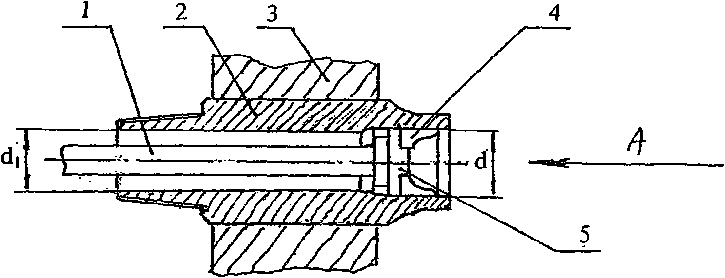
[0012] The drill pipe friction welding split flap living punch of the present invention is composed of a punch 4 and a punch pad 5 . The punch 4 has multiple petals, and the multi-petal punches 4 are evenly distributed on the periphery of the punch pad 5 .

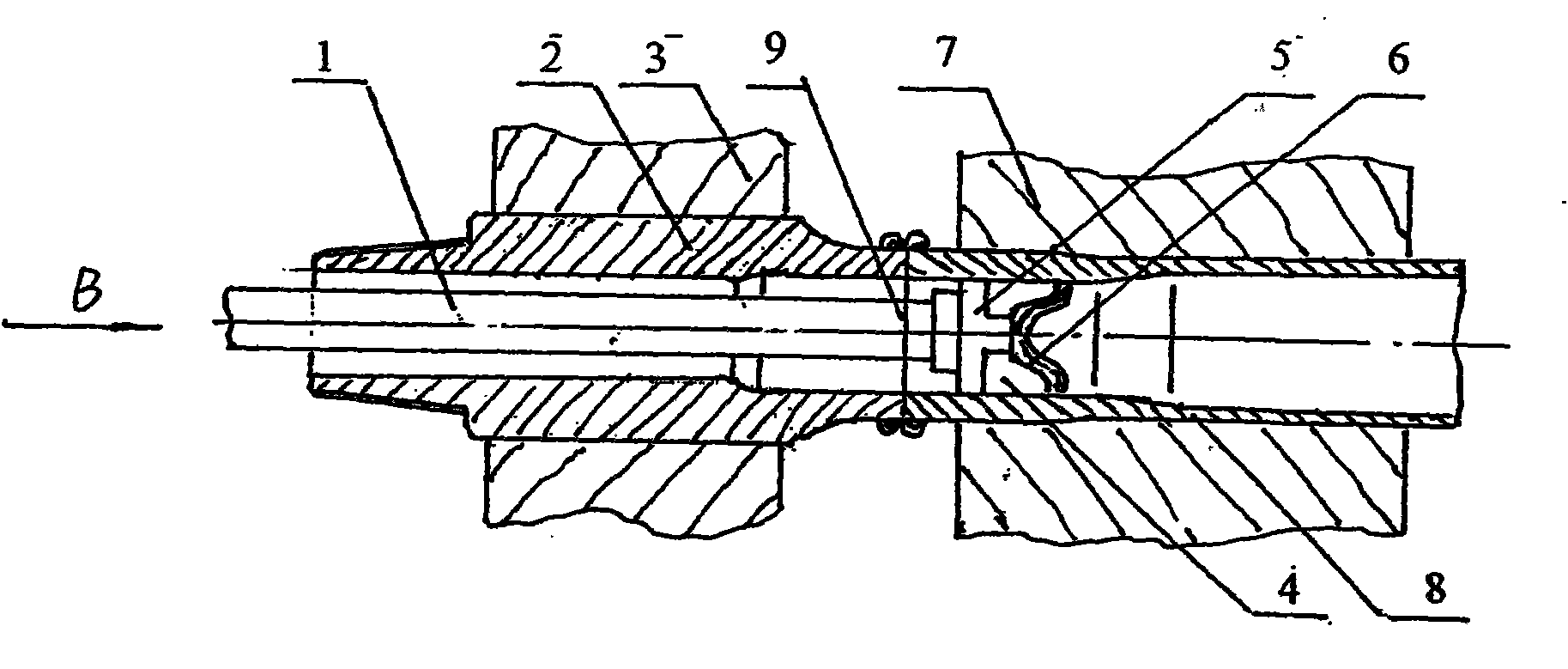
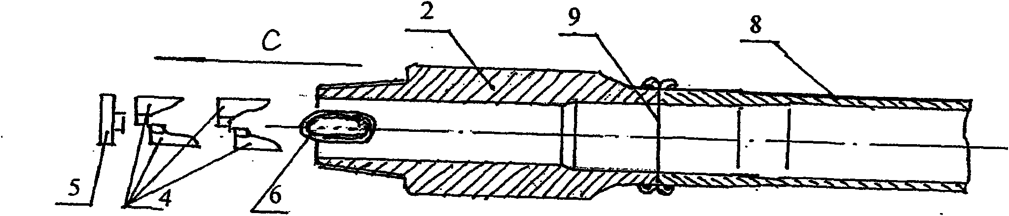
[0013] When in use, the live punch of the split valve of the present invention is pre-installed on one end of the large aperture of the male joint 2 to be welded ( figure 1 middle d), such as figure 1 ;As long as the selection is smaller than the hole diameter of the threaded end of the male connector (d 1 ) of the punch rod 1, can realize the inner punching of the male joint inner flash 6; figure 2 , the split live punch can be designed into different shapes according to the diameter of the male joint, so that the inner flash can be cut into several sections or elongated into an ellipse, which is similar to a saddle-shaped overall inner flash ring. The small diameter of the ellipse is smaller than the minimum inner dia...


PUM


Abstract

The invention relates to a drill stem friction welding valving movable punch which is used for punching an inner flash formed by friction welding of a drill stem. The valving movable punch comprises a plurality of valves of punches (4) and a punch cushion (5), wherein the punches are uniformly distributed at the periphery of the punch cushion (5). The inner flash punched by adopting the drill stem friction welding valving movable punch is easy to take out from a small diameter end of a male connector.

Description

(1) Technical field [0001] The invention relates to a drill pipe friction welding flap live punch. It is used to wash away the inner flash formed by friction welding of drill pipe. It belongs to the technical field of oil drill pipe manufacturing. (2) Background technology [0002] The manufacturing method of the drill pipe is to connect the pipe body with the male joint and the female joint through friction welding. The internal flash formed by welding is flushed out after welding through the punch protruding from the spindle hole on the welding machine, and the flash and punch must be removed from the drill pipe. Due to the design structure of the drill pipe, the female joint is a through hole, and the male joint is generally not a through hole. One end of the tapered thread has a small diameter, and the welding end has a large diameter. The inner hole has a stepped structure. The method is easy to solve, that is, the punching knife is fixed on the punching rod, the pun...

Claims


Application Information

Patent Timeline
Patent Type & Authority Applications(China)
IPC IPC(8): B23D27/00
Inventor 朱庆华郭磊
Owner 江阴兴鼎石油管具有限公司
Why Eureka
Try Eureka