
Micro-channel heat exchanger and equipment using same

A micro-channel heat exchanger and channel technology, applied in indirect heat exchangers, heat exchange equipment, heat exchanger types, etc., can solve problems such as poor drainage of condensed water, improve drainage effect, facilitate mass production, and improve overall simple structure

Active Publication Date: 2011-03-30
GOLDEN DRAGON PRECISE COPPER TUBE GROUP +1
View PDF11 Cites 16 Cited by
  • Summary
  • Abstract
  • Description
  • Claims
  • Application Information

AI Technical Summary

Problems solved by technology

[0007] The invention provides a microchannel heat exchanger to solve the problem of poor discharge of condensed water in the existing microchannel heat exchanger

Method used


Image

  • Micro-channel heat exchanger and equipment using same
  • Micro-channel heat exchanger and equipment using same
  • Micro-channel heat exchanger and equipment using same

Examples


Embodiment Construction

[0032] In the following description, numerous specific details are set forth in order to provide a thorough understanding of the present invention. However, the present invention can be implemented in many other ways different from those described here, and those skilled in the art can make similar extensions without violating the connotation of the present invention, so the present invention is not limited by the specific implementations disclosed below.

[0033] The microchannel heat exchanger of the present invention will be described below with reference to the accompanying drawings.

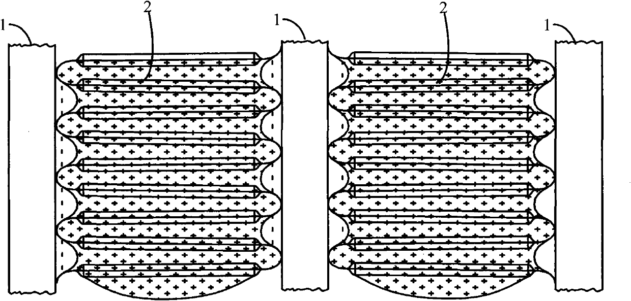
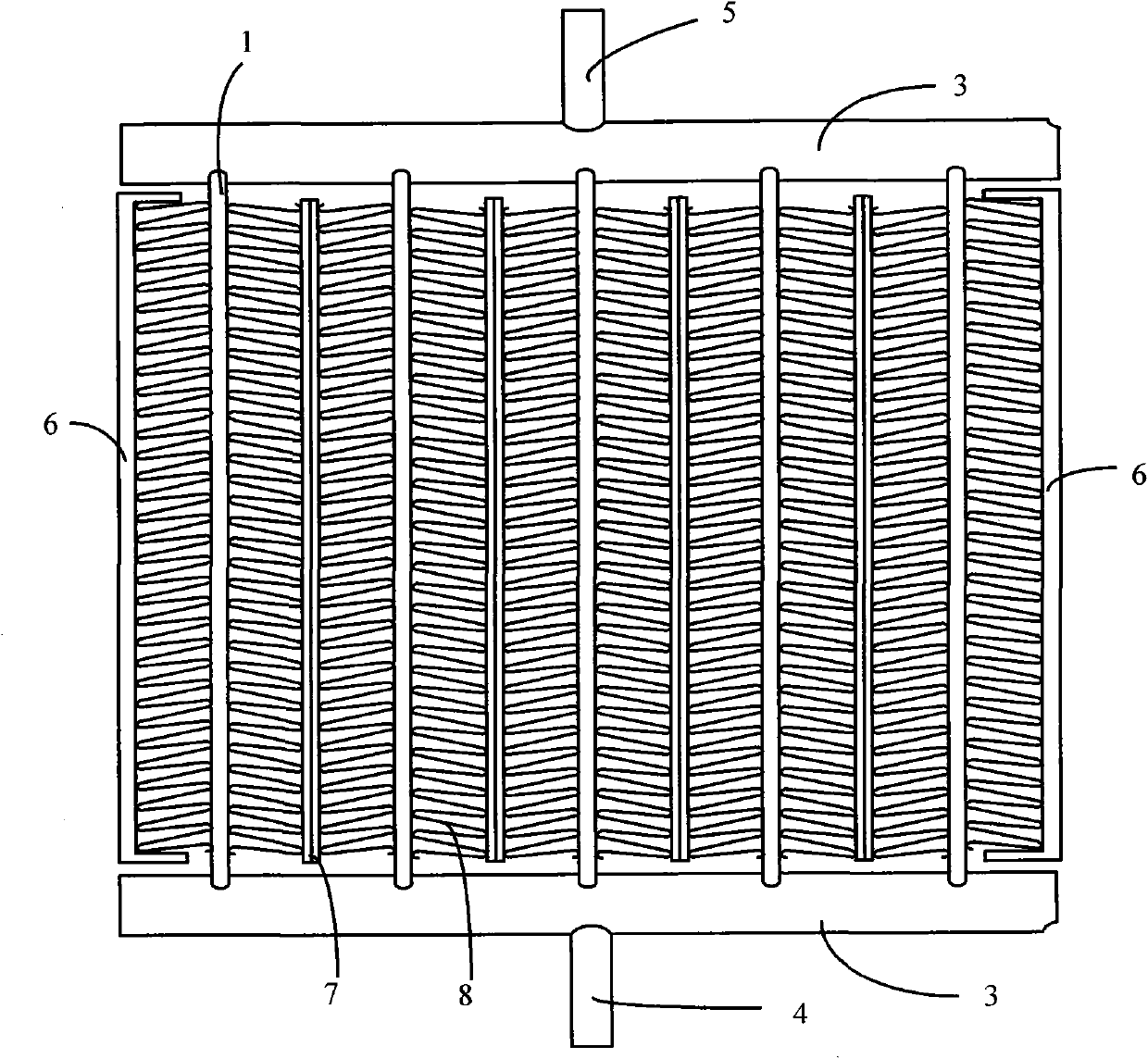
[0034] image 3 It is a structural schematic diagram of an embodiment of the microchannel heat exchanger of the present invention, Figure 4 for image 3 A partial schematic of the , used to illustrate how it drains.

[0035] Please refer to image 3 , In an embodiment of the present invention, the microchannel heat exchanger includes a flat tube 1 , corrugated fins 8 , water guide fins ...


PUM


Abstract

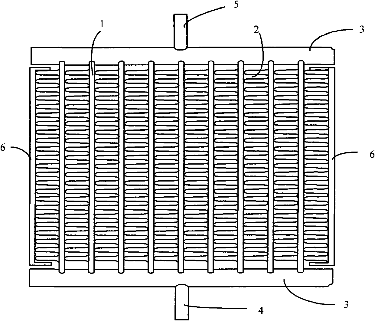
The invention relates to a micro-channel heat exchanger. The micro-channel heat exchanger comprises a plurality of flat pipes which are arranged parallelly along a direction vertical to the ventilation direction, and hollow collecting pipes which are arranged at the two ends of each flat pipe, wherein a heat exchange medium channel is formed in each flat pipe; the ends of the flat pipes are inserted into the hollow collecting pipes; the heat exchange medium channels of the flat pipes are communicated with hollow channels of the hollow collecting pipes; a water guide plate or a water guide sheet is arranged between two adjacent flat pipes and provided with a condensed water flow channel; and a ripple fin is arranged between the water guide plate or the water guide sheet and the adjacent flat pipe. The micro-channel heat exchanger can obviously improve the drainage effect. The invention also provides equipment using the micro-channel heat exchanger.

Description

technical field [0001] The invention relates to the technical field of heat exchangers, in particular to a microchannel heat exchanger. The invention also relates to a device using the micro-channel heat exchanger, such as an air-cooled air conditioner or a heat pump. Background technique [0002] In an air-cooled air-conditioning system, when the heat exchanger is used as an evaporator, the water vapor in the air will condense on the surface of the heat exchanger, and the condensed water will reduce the heat transfer performance of the heat exchanger and increase the wind resistance. It may also cause "water dripping" in the air conditioner. When the heat exchanger is used in the outdoor unit of the heat pump, the surface of the outdoor heat exchanger will also condense or frost under heating conditions. When the frost builds up to a certain extent, the air conditioner needs to start the defrosting mode to melt the frost in the outdoor heat exchanger, and the melted water...

Claims


Application Information

Patent Timeline
IPC IPC(8): F28D1/04F25B39/02F24F13/22
CPCF28F17/005F28D1/05366
Inventor 张杰山
Owner GOLDEN DRAGON PRECISE COPPER TUBE GROUP
Learn More