
Electric control board testing platform with detection signal and power supply isolation function

A technology for signal detection and power isolation. It is used in electronic circuit testing, voltage/current isolation, and current/voltage measurement. It can solve problems such as poor accuracy, chip damage, and lack of signal isolation.

Inactive Publication Date: 2011-03-30
FOSHAN ZHONGGEWEI ELECTRONICS
View PDF6 Cites 10 Cited by
  • Summary
  • Abstract
  • Description
  • Claims
  • Application Information

AI Technical Summary

Problems solved by technology

[0002] Traditional signal detection equipment generally does not take signal isolation measures, that is, the detection signal is directly connected to the I / O port of the single-chip microcomputer, and the detected data is also displayed through the instrument. Although this method is simple and practical, whether it is safety or less accurate
If the input voltage signal exceeds the rated value of the I / O port of the single-chip microcomputer, it will cause damage to the chip; although some test circuits have also taken some protective measures, such as limiting and clamping the input signal, it cannot completely solve the problem of safety. question

Method used


Image

  • Electric control board testing platform with detection signal and power supply isolation function
  • Electric control board testing platform with detection signal and power supply isolation function
  • Electric control board testing platform with detection signal and power supply isolation function

Examples


Embodiment Construction

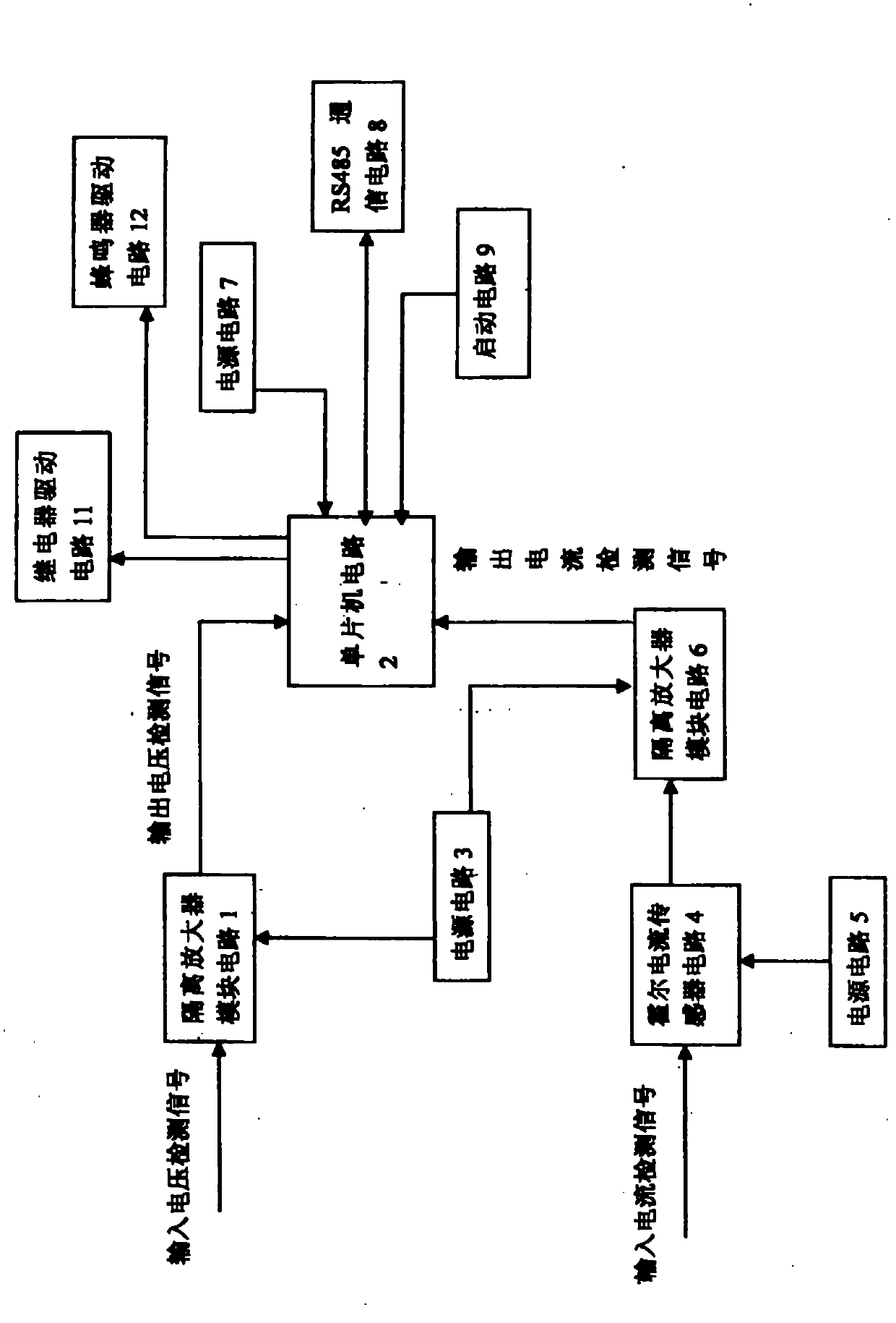
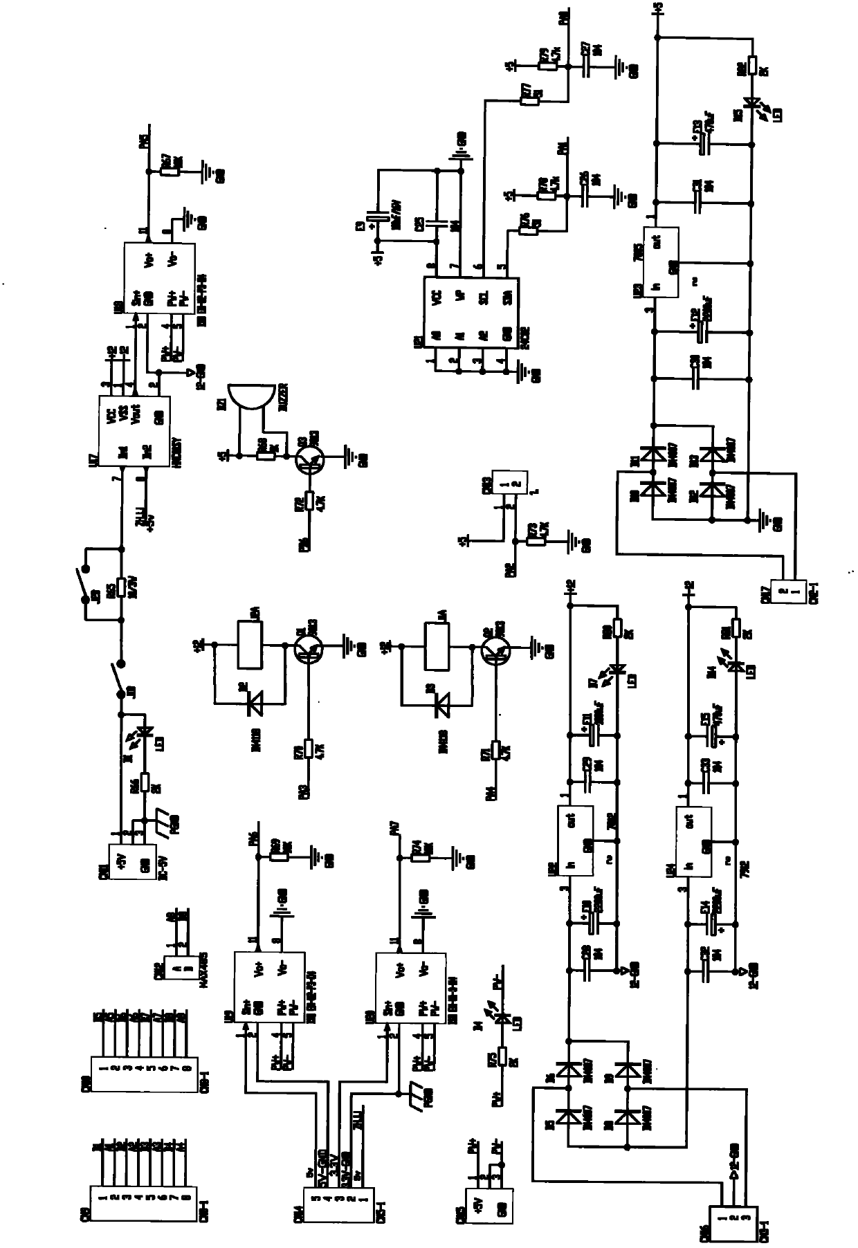
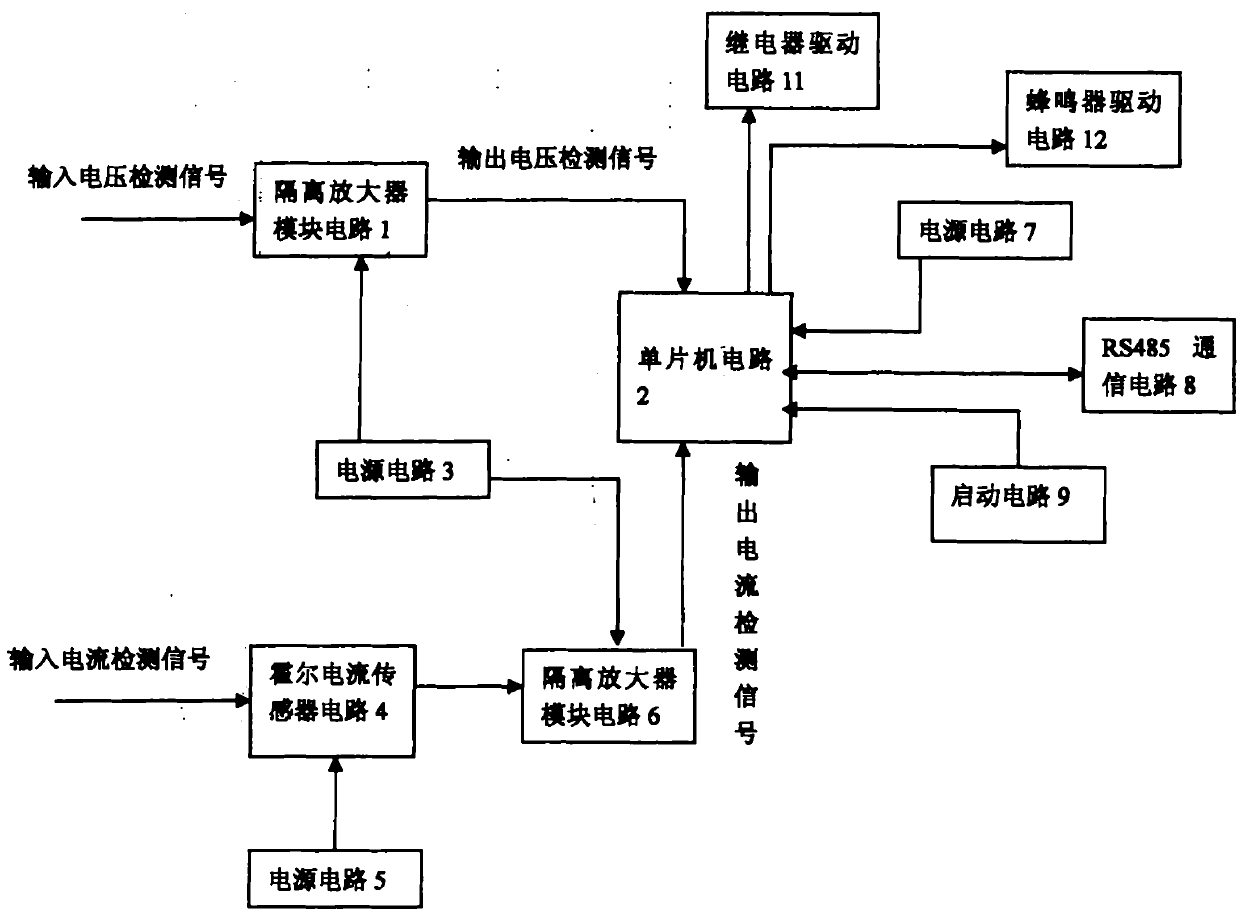
[0010] Attached below figure 1 And attached figure 2 The present invention is further described, and the preferred embodiment of the present invention is: the electric control board test platform with detection signal and power isolation function described in this embodiment includes a third power supply circuit 3, a single-chip microcomputer circuit 2, and a relay drive circuit 11 , buzzer drive circuit 12, RS485 communication circuit 8, start-up circuit 9, first isolation amplifier module circuit 1, Hall current sensor circuit 4, wherein, the input terminal of the first isolation amplifier module circuit 1 is connected with the input voltage detection signal , the signal output end is connected with the single-chip microcomputer circuit 2; the input end of the Hall current sensor circuit 4 is connected with the input current detection signal, the output end is connected with the signal input end of the second isolation amplifier module circuit 6, and the second isolation am...


PUM


Abstract

The invention provides a dynamic tester with a detection signal and power supply isolation function. The tester comprises an RS485 communication circuit, a starting circuit and a Hall current sensor circuit, wherein an input end of a first isolated amplifier module circuit is connected with an input voltage detection signal, and a signal output end is connected with a singlechip circuit; an inputend of the Hall current sensor circuit is connected with an input current detection signal, and an output end of the Hall current sensor circuit is connected with a signal input end of a second isolated amplifier module circuit; an output end of the second isolated amplifier module circuit is connected with the singlechip circuit; the RS485 communication circuit, the starting circuit, a relay starting circuit and a buzzer starting circuit are respectively connected with the singlechip circuit; a third power circuit is connected with the first isolated amplifier module circuit and the second isolated amplifier module circuit; a fifth power circuit is connected with the Hall current sensor circuit; and a seventh power circuit is connected with the singlechip circuit and the RS485 communication circuit. The scheme guarantees full isolation of input and output signals with power supply, over-voltage cannot occur, and the safety is greatly improved.

Description

Technical field: [0001] The invention relates to the technical field of circuit detection, in particular to an electric control board test platform with detection signal and power isolation functions. Background technique: [0002] Traditional signal detection equipment generally does not take signal isolation measures, that is, the detection signal is directly connected to the I / O port of the single-chip microcomputer, and the detected data is also displayed through the instrument. Although this method is simple and practical, whether it is safety or Accuracy is poor. If the input voltage signal exceeds the rated value of the I / O port of the single-chip microcomputer, it will cause damage to the chip; although some test circuits have also taken some protective measures, such as limiting and clamping the input signal, it cannot completely solve the problem of safety. question. Industrial production sites often have harsh conditions, and various unexpected situations may oc...

Claims


Application Information

Patent Timeline
IPC IPC(8): G01R31/28G01R19/00G01R15/14
Inventor 黄涛刘志辉刘燕罗高诚余梦林王健才肖静吴明剑邱小辉吴卫恒
Owner FOSHAN ZHONGGEWEI ELECTRONICS
Learn More