
Multi-probe unit

A multi-probe and substrate technology, applied in the field of multi-probe units, to shorten the setup process and reduce the inspection cost

Inactive Publication Date: 2011-03-30
KLT
View PDF0 Cites 14 Cited by
  • Summary
  • Abstract
  • Description
  • Claims
  • Application Information

AI Technical Summary

Problems solved by technology

[0013] However, the above cell setup process requires a 1:1 configuration of the pads of the LCD panel and the pins of the detector cell, requiring several hours of work time

Method used


Image

  • Multi-probe unit
  • Multi-probe unit
  • Multi-probe unit

Examples


Embodiment Construction

[0030] The structure of the multi-probe unit involved in the present invention will be described in detail below with reference to the accompanying drawings.

[0031] In the following description, for well-known related functions or structures, if it is considered that the detailed description may obscure the understanding of the main idea of ​​the present invention, the detailed description will be omitted. In addition, the terms used below are defined on the basis of the functions of the present invention, and may vary depending on the user's intention or custom. Therefore, its definition should be understood on the basis of the entire content of this specification.

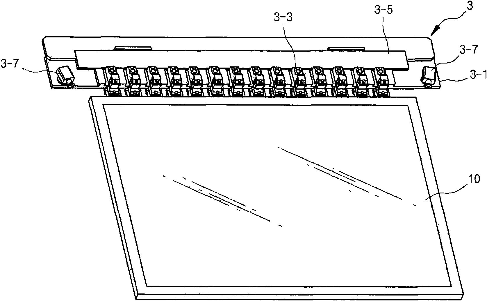
[0032] Figure 4 It is an oblique view of the composition structure of the multi-probe unit involved in the present invention, Figure 5 It is an exploded oblique view of the composition structure of the multi-probe unit involved in the present invention, Figure 6 is along Figure 4 The cross-sectional vie...


PUM


Abstract

Disclosed is a multi-probe unit, including a rectangle substrate, made of metallic material, fixed on a LCD detection device, and having aligning cameras on two ends in a length direction; a linear motor, arranged on the substrate along a length direction and having a plurality of moving bodies; a movable stand, one end of which is fixed to the moving bodies through linear racks, and the other end is fixedly provided with a probe module: a pair of LM guide ways, arranged on the substrate by interval in a length direction; an encoder, provided with a graduated scale between the LM guide ways, and a nagnetic head on a bottom face of the movable stand; a rectangle outer housing, made of metal or synthetic resin, and fixed on the upper end of the substrate through a fixed rod; a data PCB, arranged on a top face of the substrate through a fixed rack. The multi-probe unit is capable of shortening a setting process of a detector unit, detecting various LCD boards by one detector unit, and reducing cost of detection.

Description

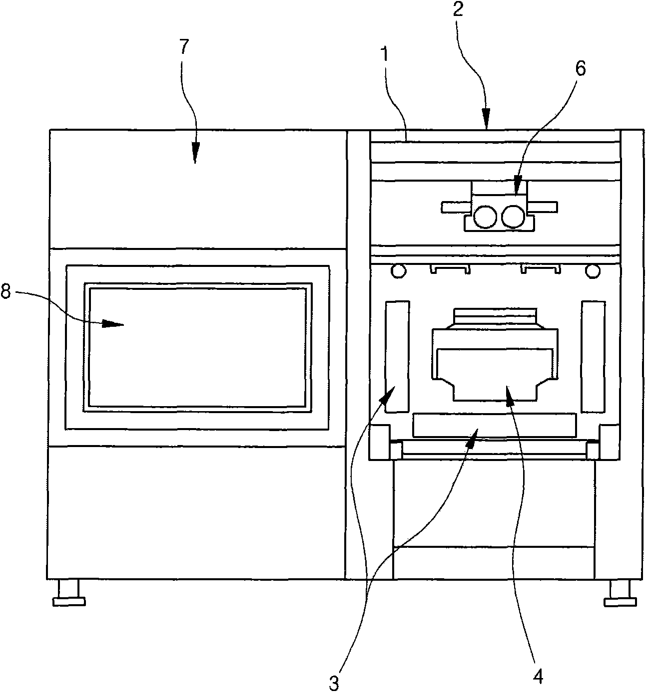
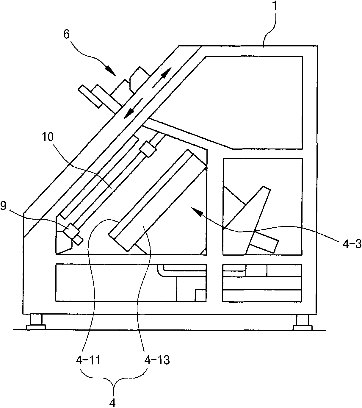
technical field [0001] The present invention relates to a multi-probe unit, in particular to a liquid crystal display (LCD) panel of various specifications, which can automatically move each probe module according to the LCD panel of the corresponding specification symmetrically on the substrate through a linear motor. unit. Background technique [0002] Generally speaking, LCD testing equipment refers to the automatic transmission of the LCD panel to the location of the staff, so that the staff can use the naked eye to distinguish whether the LCD panel is a defective product or a qualified product, and after the test is completed, according to the test result, the LCD Boards are divided into good products (good), repair objects (repair) and scrap products (reject), and they are stacked in the corresponding equipment in the box (cassette). [0003] Such as figure 1 and figure 2 As shown, a general LCD inspection device is provided with a detection unit 2 for detecting th...

Claims


Application Information

Patent Timeline
Patent Type & Authority Applications(China)
IPC IPC(8): G02F1/13
CPCG01R1/0466G01R1/073G01R31/2879G01R31/2886G09G3/006G09G3/20
Inventor 李相龙朴玄相
Owner KLT
Learn More