Halogen lamp circuit

A halogen lamp and circuit technology, applied in the direction of electric light sources, electrical components, lighting devices, etc., can solve the problems of short service life, low color temperature, low luminous efficiency, etc., and achieve the effect of wide application range

Inactive Publication Date: 2011-03-30
蒋金钟
View PDF0 Cites 0 Cited by
  • Summary
  • Abstract
  • Description
  • Claims
  • Application Information

AI Technical Summary

Problems solved by technology

[0002] Incandescent lamps have many advantages: simplicity, low cost, easy adjustment and control of brightness, good color rendering (Ra=100), etc., but at the same time there are many fatal disadvantages: such as short service life, low luminous efficiency (only 12%-18% can be converted into light energy, while the rest is lost in the form of heat energy), low color temperature (2700-3100K)
Halogen bulbs have greatly improved these shortcomings on the basis of retaining the above advantages, so halogen lamps have been widely used in some places, but the circuits used by halogen lamps have not changed, which limits the use of halogen lamps.

Method used


Image

  • Halogen lamp circuit
  • Halogen lamp circuit

Examples


Embodiment Construction

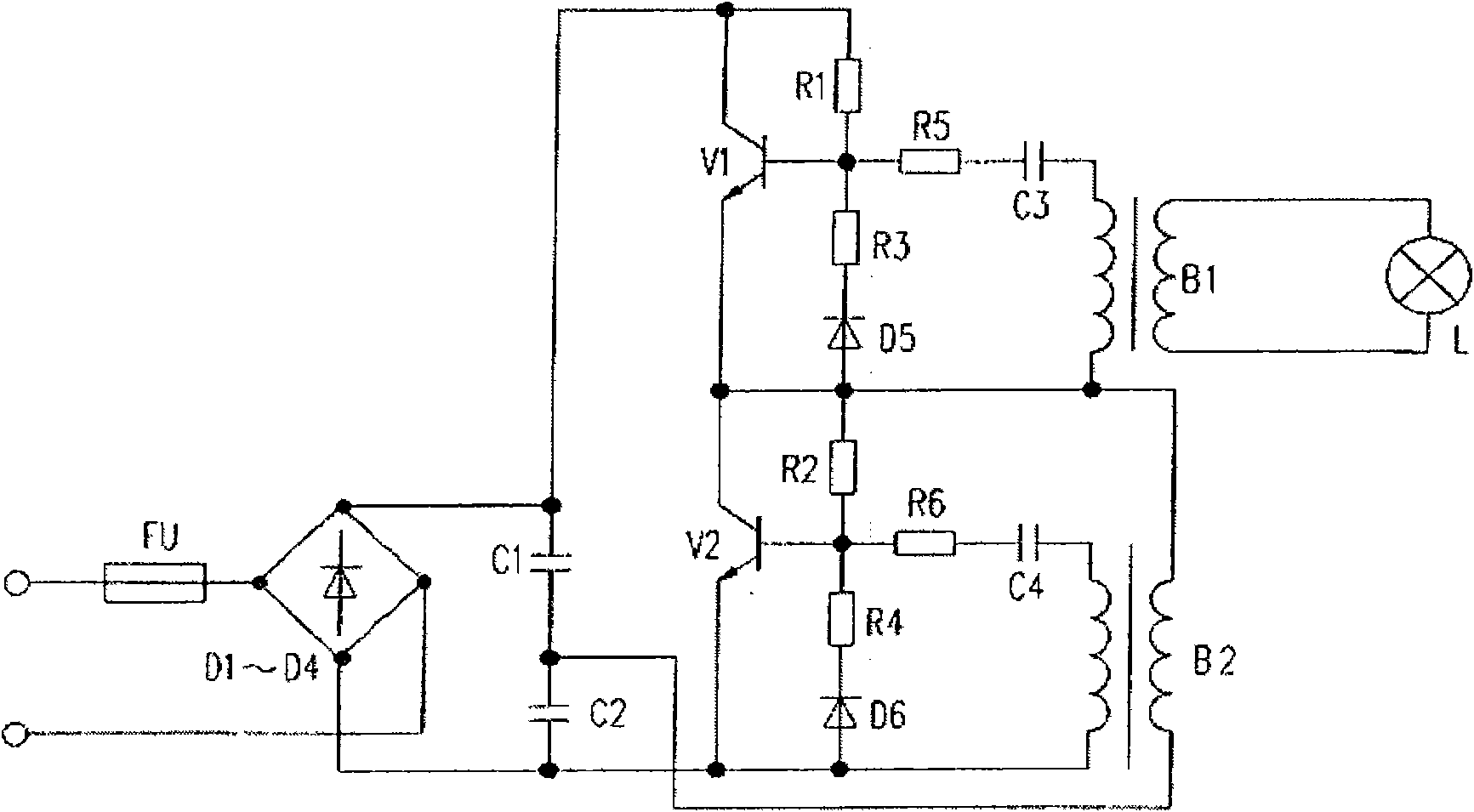
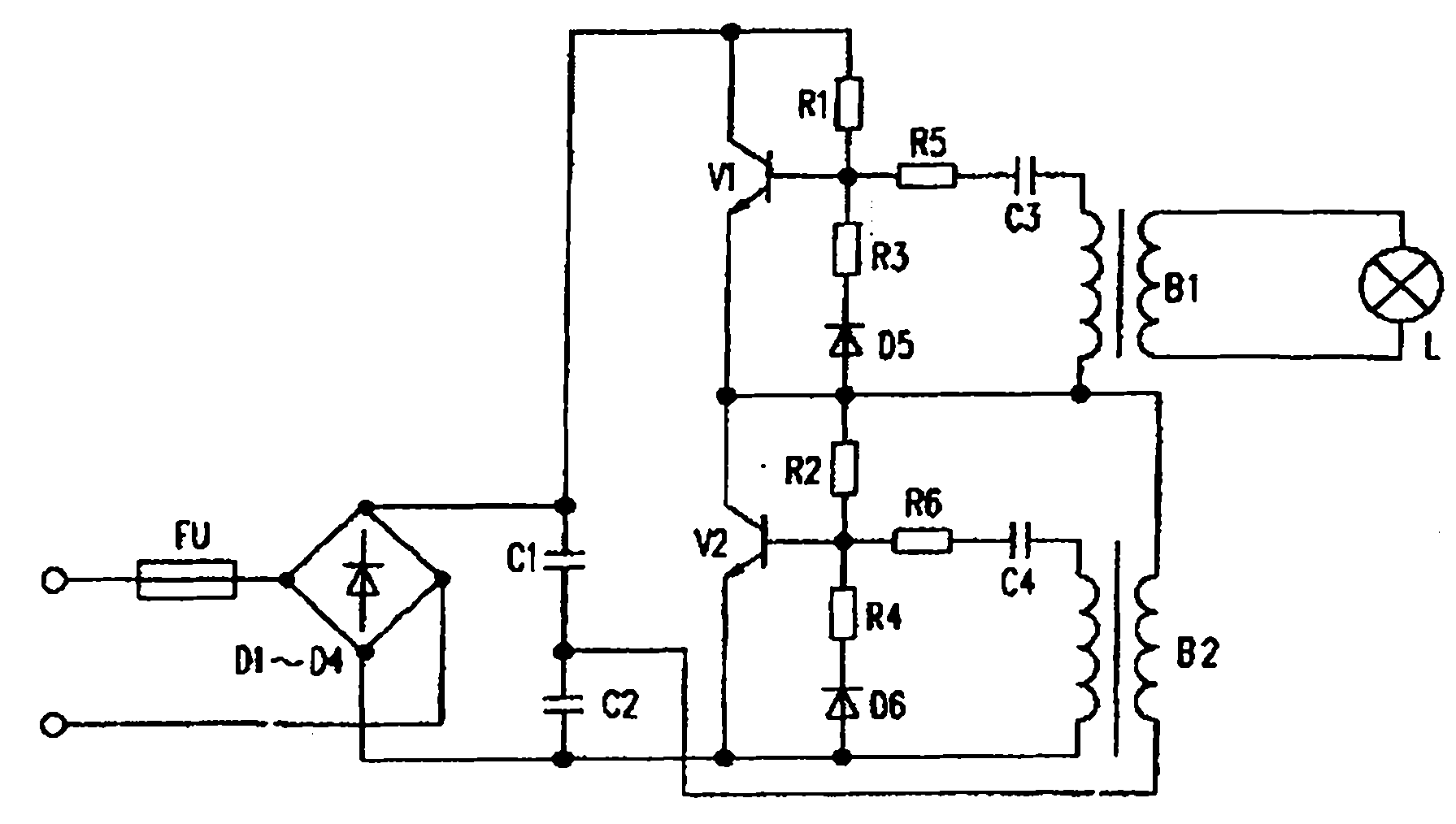
[0008] The present invention includes fuse FU, rectifier bridge D1-D4, capacitor C1, C2, C3, C4, resistor R1, R2, R3, R4, R5, R6, triode V1, V2, transformer B1, B2 and lamp L, rectifier bridge D1 The positive AC input terminals of ~ D4 are connected to the power supply through the fuse FU, the positive DC output terminals of the rectifier bridges D1 ~ D4 are respectively connected with the first capacitor C1, the collector of the first triode V1 and the first resistor R1, and the rectifier bridge D1 The negative DC output terminals of ~ D4 are respectively connected with the second capacitor C2, the emitter of the second transistor V2, the sixth diode D6 and the negative input terminal of the second transformer B2, and the emitter of the first transistor V1 Respectively connected with the collector of the second triode V2, the positive pole of the fifth diode D5, the negative input terminal of the second resistor R2, the negative input terminal of the first transformer B1 and t...


PUM


Abstract

The invention relates to the improvement of a lamp circuit structure, in particular to a halogen lamp circuit. Aiming at the problem, the invention provides the halogen lamp circuit which does not limit the application of a halogen lamp. The halogen lamp circuit comprises a fuse, a rectifier bridge, a capacitor, a resistor, a triode, a transformer and a lamp.

Description

Technical field: [0001] The present invention relates to the improvement of lamp circuit structure, in particular to a halogen lamp circuit. Background technique: [0002] Incandescent lamps have many advantages: simplicity, low cost, easy adjustment and control of brightness, good color rendering (Ra=100), etc., but at the same time there are many fatal disadvantages: such as short service life, low luminous efficiency (only 12%-18% can be converted into light energy, while the rest is lost in the form of heat energy), and the color temperature is low (2700-3100K). Halogen bulbs have greatly improved these disadvantages on the basis of retaining the above advantages, so halogen lamps have been widely used in some places, but the circuits used by halogen lamps have not changed, which limits the use of halogen lamps. Invention content: [0003] The present invention aims at the above problems and provides a halogen lamp circuit which does not limit the use of the halogen l...

Claims


Application Information

Patent Timeline
Patent Type & Authority Applications(China)
IPC IPC(8): H05B39/00
Inventor 蒋金钟
Owner 蒋金钟
Why Eureka
Try Eureka