Multi-use fluid collection and transport apparatus

a technology of fluid collection and transportation apparatus, applied in the direction of sewer system, sewage draining, construction, etc., can solve the problems of inability to provide a system or assembly with short of providing a system or assembly that has a broad spectrum of use, and high cost, and achieves convenient collection and removal (transport), easy application of innovation, and convenient use.

Inactive Publication Date: 2005-03-17
PARKER ALTON F
View PDF6 Cites 10 Cited by
  • Summary
  • Abstract
  • Description
  • Claims
  • Application Information

AI Technical Summary

Benefits of technology

[0037] The deficiencies and limitations of the earlier art, namely complexity, cost and in most instances inflexibility, are overcome by providing an inexpensive, easily applied innovation that facilitates collection and removal (transport) of subsurface or sub-structural waters. Additionally, a continued rollup or wrap-around capability of the instant drainage assembly enhances it greatly in respect of packaging and shipping, as well as use in the field.
[0038] Defined generally by a sandwich morphology, the invention consists of a planar array of strong, firm, non-biodegradable members that are, in a pristine sense, configured as supportive, stand-off elements that bear a membranous covering of geo-textile filter fabric, on at least one face of the array. Depending on the use of this relatively flexible assembly, the other face of the planar array may bear the same type of membranous covering, a non-permeable covering or no covering at all, save for an optional mesh. The latter (mesh) is employed, at a manufacturer's discretion, to enhance the structural integrity of the assembly.
[0039] Critical to the synthesis of the invention is the use of discrete elements, of a generally circular (hoop) definition. These elements are concatenated, to form a coil, or are ganged in a coaxial arrangement along a membrane, fixed thereto or integral with at least one longeron. Both of these constructs give the resultant (member) a tunnel-like or quasi-tubular shape and, when arrayed by parallel alignment or cross-linking, possess excellent flexibility, provide exceptional overburden support and facilitate fluid transport, after its passage through the overlying filter fabric.
[0041] With the invention, there is acquired not only a device that has unlimited in-ground use, with high overburden sustainability, but one retaining a high degree of flexibility that allows wrapping about an article / structure or compact rolling-up, for ease in handling, storage and shipment.

Problems solved by technology

Ground water seepage remains a problem in most non-arid regions of the world; and, building footings, garage floors (multi-level) and walls, facing surface and subsurface waters, have been most susceptible to water incursions.
Many attempts have thus been made to create drainage mechanisms that will take advantage of new materials for filtration, but nonetheless have fallen short of providing a system or assembly that has a broad spectrum of usage (“multi-usage”), such as for placement on vertical surfaces, under concrete floors (above and below ground) and for wrapping around structures such as conduits.
However, it is in the careful study of each disclosure that one perceives, albeit suitability for intended purpose, its limitations in broad spectrum applicability, as noted above.
The apparatus' outer sheets are both porous and not suitable for placement against vertical walls.
Most limiting is the necessity for the fibrous “filling” in which the tubules are embedded.
When used for the specific purpose shown in '686, and notwithstanding the “filling”, the apparatus appears to enjoy some flexibility; however, it seems intuitive that doubling the thickness of the “sandwich” would render such flexibility problematical.
Although more stylized emplacements can be conceived for the apparatus, it appears that in the vertical drainage mode, turning of comers is impossible because the longitudinal fixation denies flexibility, as defined and required by the instant inventor.
The latter characteristic obviates coil interference during destruction (by grinding) of the tarmac.
This apparatus requires a considerable thickness (and amount) of non-woven mat, making it unsuitable for the purposes of draining most structures.
It also appears to lack the degree of flexibility required by the instant inventor.
Placed in a horizontal position, the spring gap variations of this element would defeat its purpose in any planar filtration ensemble.

Method used


Image

  • Multi-use fluid collection and transport apparatus
  • Multi-use fluid collection and transport apparatus
  • Multi-use fluid collection and transport apparatus

Examples


Embodiment Construction

[0055] Before commencing this description, the reader is referred to the DEFINITIONS, given above. The materials of construction are well known in the industry and no further mention will be made of them other than that the filter fabric is in common usage, in sheet (“membrane”) and mat forms, and the support or stand-off elements may be composed of any strong, non-biodegradable resin or polymeric, such as polyamide, polyester or polyvinyl chloride. In short, the physical characteristics of the materials comprising the stand-off elements should be heat-melt formable to facilitate manufacture by extrusion, casting or injection molding processes.

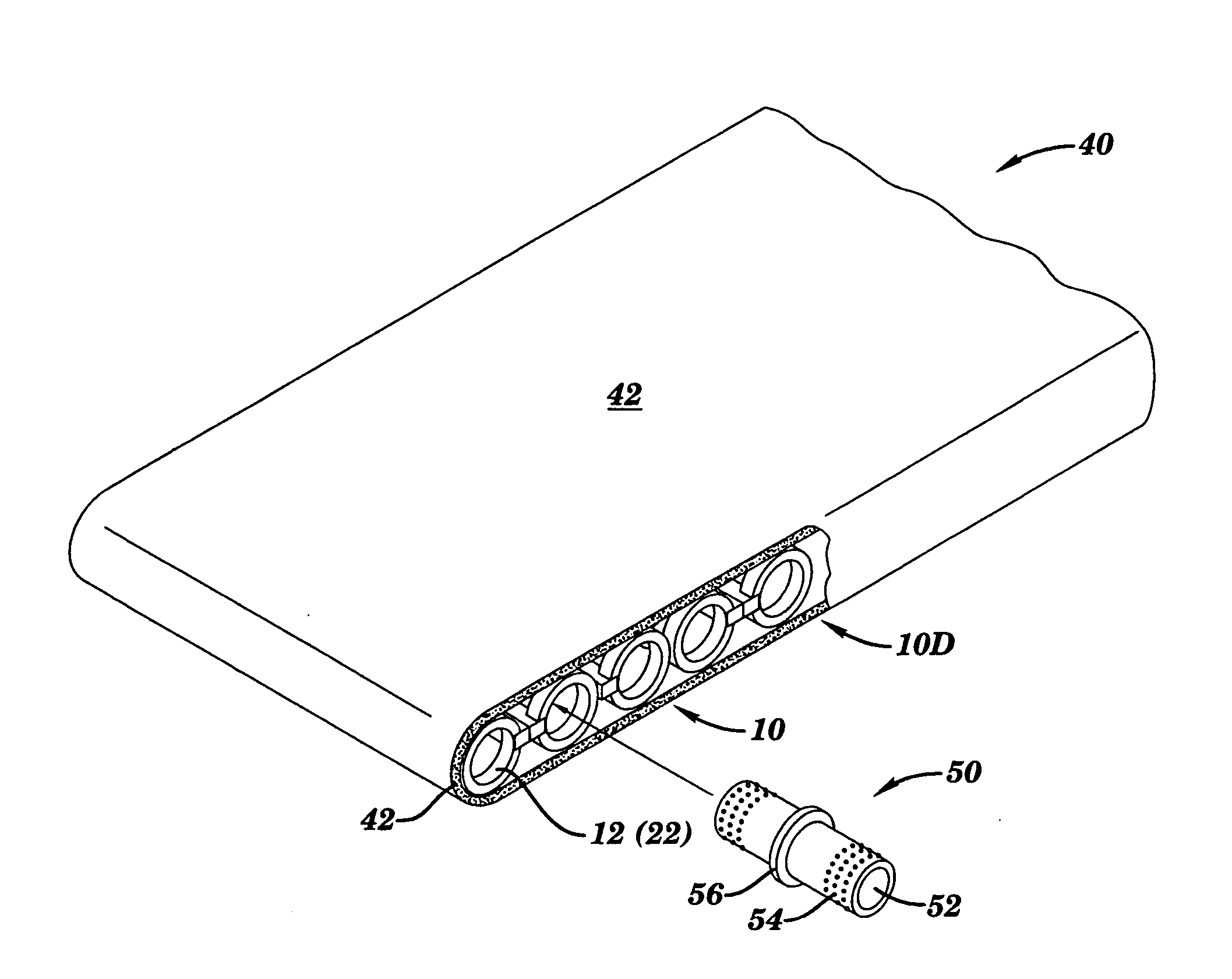
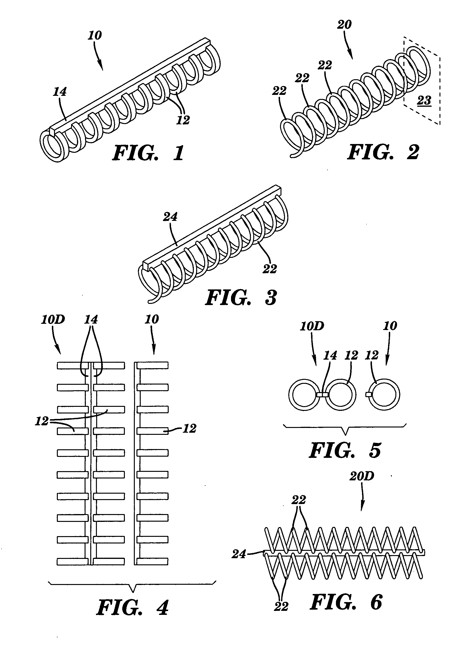
[0056] Referring now to FIG. 1, there is depicted, in the preferred embodiment, a support / stand-off element 10 of the invention. It is, substantially, a quasi-tubular item comprised of a series of hoops or rings 12 that are axially aligned on and integral with a stringer / longeron 14. This element is generally produced by injection molding as ...


PUM


Abstract

A non-biodegradable, unitary drainage device of highly flexible character. The invention features a monolithic, sandwich construct consisting of membranous, planar top and, optional-use, bottom sheets which form a wrap / envelope or covering on a planar array of quasi-tubular supports or “stand-off” elements. Actual positioning of the supports in their planar array is varied, with parallel-interleaving, cross-linking and intertwining of supports, of either or both embodiments, being done to acquire varying degrees of strength and flexibility. Depending on specific function to be performed, the covering sheet(s) may be of differing materials, for either particulate filtering or fluid impermeability (sealing). A connection adjunct is provided that allows direct fluid communication from support(s) of one such monolith to another.

Description

CROSS-REFERENCES TO RELATED APPLICATIONS [0001] This application is a Continuation-in-Part of U.S. patent application Ser. No. 10 / 663,110, filed on Sep. 16, 2003, by the same inventor, for SUBTERRANEAN DRAIN DEVICE WITH IMPROVED FILTER, and for which priority under 35 USC 119(e) and 120 is hereby claimed.STATEMENT REGARDING FEDERALLY SPONSORED RESEARCH OR DEVELOPMENT [0002] Not Applicable BACKGROUND OF THE INVENTION [0003] 1. Field of the Invention [0004] This invention relates generally to devices and constructs used to effect subterranean drainage from building structures and entrenchments, such as walls, footings and foundations, where seepage and ground water are a problem, and also under garage and basement floors where overburden of concrete exacerbates the drainage problem by frustrating most existing devices or their filtering adjuncts. More specifically, this invention embodies a filtered drain improvement using a simplified fabric separation device that requires a far less...

Claims


Application Information

Patent Timeline
Patent Type & Authority Applications(United States)
IPC IPC(8): E02B11/00
CPCE02B11/005
Inventor PARKER, ALTON F.
Owner PARKER ALTON F
Why Eureka
Try Eureka