Dedicated dust removal device for dry sand-grinding dust removal complete equipment and dust removal method

A complete set of equipment and technology for dust removal devices, applied in separation methods, chemical instruments and methods, use of liquid separation agents, etc. Problems, to achieve the effect of novel structure design, reduce energy consumption and noise

Active Publication Date: 2011-04-06
ZHEJIANG SHUANGJIN MACHINERY HLDG
View PDF17 Cites 18 Cited by
  • Summary
  • Abstract
  • Description
  • Claims
  • Application Information

AI Technical Summary

Problems solved by technology

[0007] The above-mentioned background technology, first, the energy consumption required for dust removal is not only high, bu

Method used


Image

  • Dedicated dust removal device for dry sand-grinding dust removal complete equipment and dust removal method
  • Dedicated dust removal device for dry sand-grinding dust removal complete equipment and dust removal method

Examples


Embodiment 1

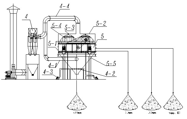
[0014] Embodiment 1: with reference to attached figure 1 . A special dedusting device for complete sets of equipment for dry sand grinding and dedusting, which includes a deduster 4 and a vibrating screen 5, and the deduster 4 is prior art. Vibrating sieve 5 both can adopt prior art, also can adopt the vibrating sieve designed by the applicant, no matter be which kind, just as the supporting assembly of the dedusting device of the present application at this. The top of the vibrating screen is provided with a water mist pressure dust suction cover 5-2, and the water mist pressure dust suction cover 5-2 is provided with a feeding port and a dust suction port, and the dust suction port is connected with the air suction pipe 4-4. The dust collector 4 is connected, and the water mist pressure dust suction cover 5-2 has one or more water mist nozzles 5-3 built in. When there are two water mist nozzles 5-3, the two water mist nozzles 5- 3 are arranged at intervals and one side of ...

Embodiment 2

[0015] Embodiment 2: On the basis of Embodiment 1, a dust removal method for a special dust removal device for dry sand grinding and dust removal complete sets of equipment, the water mist pressure dust suction cover 5-2 located on the vibrating screening mechanism, the dust produced in the crushing process The dust is first covered by the water mist cover 5-4 produced by the water mist nozzle 5-3, so that it falls to the vibrating screen 5-1, and the trace dust not covered by the water mist cover 5-4 is covered by the water mist. Dust pressure suction hood 5-2 sucks the suction pipe 4-4 into the dust remover 4 to remove dust. At this time, the suction in the inverted cone dust suction hood 5-5 located below the vibrating screening mechanism (the outlet of the vibrating screen) The tube blows up the dust in the sand falling from the vibrating screen 5-1 and sucks it into the dust collector through the dust suction pipe 4-1 to remove dust. to stockpile.


PUM


Abstract

The invention relates to a dedicated dust removal device for dry sand-grinding dust removal complete equipment and a dust removal method. The dedicated dust removal device can effectively remove dust generated by sand grinding, and can substantially reduce energy consumption and noise, and comprises a dust remover and a vibrating screen, wherein a water mist dust pressing suction hood is arranged above the vibrating screen, and the dust suction mouth of the water mist dust pressing suction hood is communicated with the dust remover through a wind suction pipe; and the discharge port of the vibrating screen is provided with an inverted cone-shaped dust suction hood, and a dust suction pipe is arranged in the inverted cone-shaped hood and is communicated with the dust remover. The invention has the advantages that: firstly, the water mist dust pressing, the primary dust removal and the secondary dust removal in the process of sand making can be realized, and the energy consumption and the noise are greatly reduced; secondly, the clean and pure sand is obtained, and the purpose of all-weather operation is realized; and finally, in the application, the water generated when the water mist dust pressing is adopted to suck water dust can be sucked by heat energy generated by the mutual collision between sands in the process of vibrating sand screening, and can be blown by the wind, thereby obtaining dry sand with less water.

Description

technical field [0001] The invention relates to a special dedusting device and dedusting method for a complete set of equipment for dry sand milling and dedusting, which can not only effectively dedust the dust produced by sand milling, but also greatly reduce energy consumption and noise, and belongs to sand making and dedusting equipment manufacturing field. Background technique [0002] CN101362112A, name "a dry sand making method and the dry sand making machine used", including a hollow crushing working chamber (2), and a hollow dust removal working chamber (5) is provided below the crushing working chamber (2) , the upper end of the feeding channel (6) is sealed and connected with the feeding port (22), the lower end (61) of the feeding channel (6) is located in the dust removal working chamber (5), and the dust removal working chamber (5) is also provided with The air vent (7) and the air duct (8) are located in the dust removal working chamber (5), and the lower end ...

Claims


Application Information

Patent Timeline
IPC IPC(8): B02C23/00B02C23/18B01D47/06
Inventor 胡祖尧
Owner ZHEJIANG SHUANGJIN MACHINERY HLDG
Why Eureka
Try Eureka