Hand-rubbing heater

A heater and two-hand technology, applied in the field of heaters, can solve problems such as unfavorable energy saving, emission reduction, power consumption, etc.

Inactive Publication Date: 2013-04-10
南通华饰工艺品有限公司
View PDF7 Cites 0 Cited by
  • Summary
  • Abstract
  • Description
  • Claims
  • Application Information

AI Technical Summary

Problems solved by technology

[0002] At present, the electric hand heaters used by people need to consume electric energy, which is not conducive to energy saving and emission reduction

Method used


Image

  • Hand-rubbing heater

Examples


Embodiment Construction

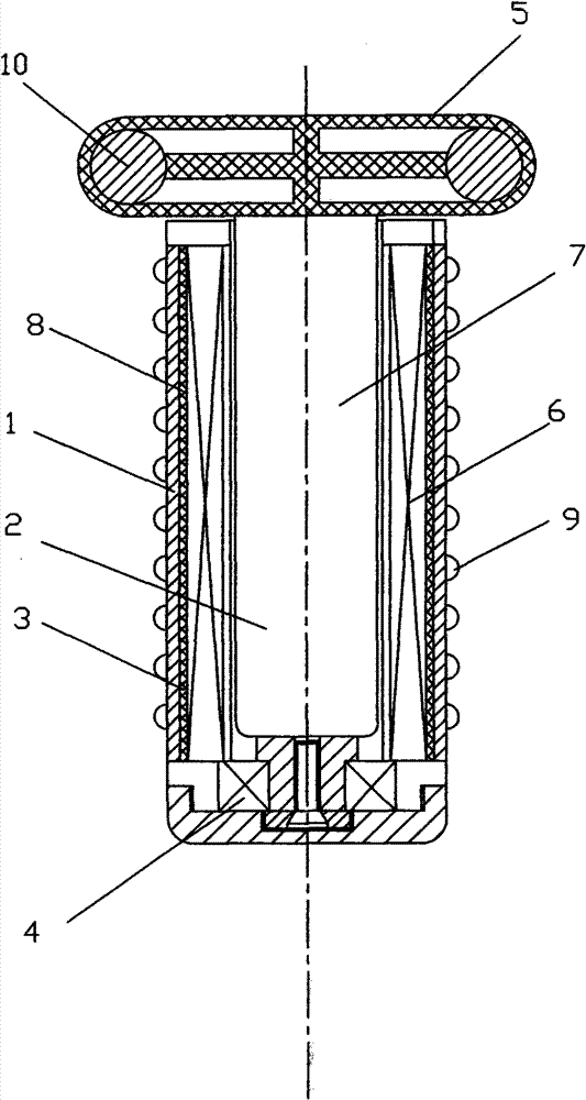
[0010] Below in conjunction with accompanying drawing and specific embodiment the present invention is further described:

[0011] figure 1 The structure diagram of the hand-rubbing warmer is shown, the hand-rubbing warmer is composed of a massage stick 1, a generator 2, an electric heating element 3, a one-way transmission wheel 4 and an inertia ring 5, and the stator 6 of the generator 2 is arranged in the massage stick 1 , the rotor 7 of the generator 2 is located in the stator 6, there is a gap between the rotor 7 and the stator 6, the upper shaft of the rotor 7 is connected to the inertia ring 2, the lower shaft of the rotor 7 is connected to the one-way transmission wheel 4, and the one-way transmission The outer circle of the wheel 4 is fixedly connected with the massage stick 1, the electric heating element 3 is arranged outside the stator 6, and a heat insulating layer 8 is arranged between the electric heating element 3 and the stator 6, and the power output line of ...


PUM


Abstract

A hand-rubbing heater is composed of a massage stick, a generator, an electric heating element, a one-way driving wheel and an inertia ring, wherein the stator of the generator is arranged in the massage stick, the rotor of the generator is arranged in the stator, a gap is left between the rotor and the stator; the upper shaft of the rotor is connected with the inertia ring, the lower shaft of the rotor is connected with the one-way driving wheel; the excircle of the one-way driving wheel is fixedly connected with the massage stick; the power output line of the generator is connected with theelectric heating element; the electric heating element is arranged outside the stator; and a thermally insulative layer is arranged between the electric heating element and the stator, thus the wasteof heat energy is reduced. The hand-rubbing heater has the functions of heating and massaging and does not use electric energy, thus facilitating energy-saving and emission reduction.

Description

technical field [0001] The invention relates to a heater, in particular to a hand-rubbing heater. Background technique [0002] At present, the electric hand heaters used by people need to consume electric energy, which is not conducive to energy saving and emission reduction. Contents of the invention [0003] The purpose of the present invention is to overcome the deficiencies of the prior art and provide a hand rubbing warmer for massaging and heating hands. [0004] The technical scheme adopted in the present invention is: the hand-rubbing warmer is composed of a massage stick, a generator, an electric heating element, a one-way transmission wheel and an inertia ring, the stator of the generator is arranged in the massage stick, and the rotor of the generator is located in the stator , there is a gap between the rotor and the stator, the upper shaft of the rotor is connected to the inertia ring, the lower shaft of the rotor is connected to the one-way transmission whe...

Claims


Application Information

Patent Timeline
Patent Type & Authority Patents(China)
IPC IPC(8): F24D13/00A61H39/04H02K7/10
Inventor 林智勇
Owner 南通华饰工艺品有限公司
Why Eureka
Try Eureka