Flooded type evaporator structure

A flooded evaporator and evaporator technology, applied in refrigeration and liquefaction, refrigeration components, refrigerators, etc., can solve the problems of gaseous refrigerants being easily entrained with liquid refrigerants, liquid shock, etc., to prevent being sucked into the compressor, and the concept is ingenious , the effect of simple structure

Inactive Publication Date: 2011-04-06
广州联合冷热设备有限公司
View PDF6 Cites 3 Cited by
  • Summary
  • Abstract
  • Description
  • Claims
  • Application Information

AI Technical Summary

Problems solved by technology

The outlet liquid blocking device of the traditional flooded evaporator adopts a flat plate. This structure makes the gaseous refrigerant evaporated in the evaporator easy to entrain the liquid refrigerant, and is brought into the compressor by the airflow at the outlet baffle, resulting in liquid shock phenomenon. possible

Method used


Image

  • Flooded type evaporator structure
  • Flooded type evaporator structure
  • Flooded type evaporator structure

Examples


Embodiment Construction

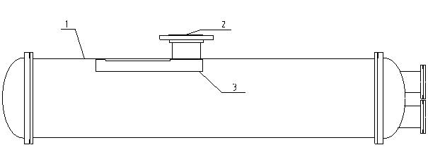
[0007] The gist of the present invention is to solve the compressor liquid hammer phenomenon caused by the unreasonable structure of the liquid baffle in the existing flooded evaporator. , Realize the secondary separation of the vapor-liquid mixture of the refrigerant in the trough-shaped liquid baffle, effectively preventing the liquid shock caused by the liquid refrigerant being sucked into the compressor. The present invention will be described in further detail below in conjunction with the accompanying drawings.

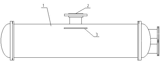
[0008] figure 1 The structural scheme adopted in the prior art is shown, including a horizontal or horizontal evaporator body 1, which is composed of a cylindrical shell and end caps at both ends, and the cavity formed by the cylindrical shell and the end caps A heat pipe immersed in liquid refrigerant is arranged inside, a gaseous refrigerant outlet pipe 2 penetrating through the shell wall is fixedly installed on the upper wall of the cylindrical shell, a...


PUM


Abstract

The invention relates to a flooded type evaporator structure, comprising a horizontal cylindrical evaporator body, wherein the upper wall in the middle of a cylindrical shell is fixedly provided with a gaseous refrigerant outlet pipe penetrating through the shell wall, a groove shape liquid baffle plate is fixedly arranged below the position of a gaseous refrigerant outlet pipe, and a backflow hole is arranged on a bottom plate of a groove. The inlet of the gaseous refrigerant outlet pipe is covered by the groove shape liquid baffle plate, the side wall of the groove shape liquid baffle plate is ought to be further provided with an inlet hole for a gaseous refrigerant and a liquid refrigerant or gas-liquid mixed refrigerant, and the inlet hole is round or oblong. The invention has the advantages of skillful design, simple and smooth structure and high practicability, by changing a simple flat panel into a semi-closed groove shape and by virtue of the gravity of liquid, the secondary separation of the gas-liquid mixture of the refrigerant is naturally realized in the groove shape liquid baffle plate, and the separated liquid refrigerant drips from the backflow hole at the bottom and evaporates again, therefore the liquid refrigerant is prevented from being sucked into a compressor.

Description

technical field [0001] The invention relates to a flooded evaporator, in particular to a structure for a liquid blocking device at the outlet of a flooded evaporator. Background technique [0002] The flooded evaporator is often used in combination with a centrifugal compressor or a screw compressor for medium and large chillers, and the system efficiency is good. In the flooded evaporator, the liquid refrigerant enters the evaporator through a throttling device, the liquid level in the evaporator is kept constant, and the heat transfer tubes in the evaporator are immersed in the refrigerant liquid. The gas-liquid mixture after endothermic evaporation still contains a large amount of liquid, so the wet vapor escaping from the evaporator must be separated from the gas-liquid before flowing back into the compressor. The outlet liquid blocking device of the traditional flooded evaporator adopts a flat plate. This structure makes the gaseous refrigerant evaporated in th...

Claims


Application Information

Patent Timeline
Patent Type & Authority Applications(China)
IPC IPC(8): F25B43/00
Inventor 王志勇
Owner 广州联合冷热设备有限公司
Why Eureka
Try Eureka