Vehicle lamp

A vehicle, reflective technology, used in motor vehicles, road vehicles, vehicle parts, etc.

Active Publication Date: 2011-04-06
VOLKSWAGEN AG
View PDF5 Cites 8 Cited by
  • Summary
  • Abstract
  • Description
  • Claims
  • Application Information

AI Technical Summary

Problems solved by technology

[0002] The problem arises in new vehicle designs that, because of the desired aerodynamics and desired design, the installation space available for the lighting unit, in particular for the lamps including taillights and headlights, is very limited

Method used


Image

  • Vehicle lamp
  • Vehicle lamp
  • Vehicle lamp

Examples


Embodiment Construction

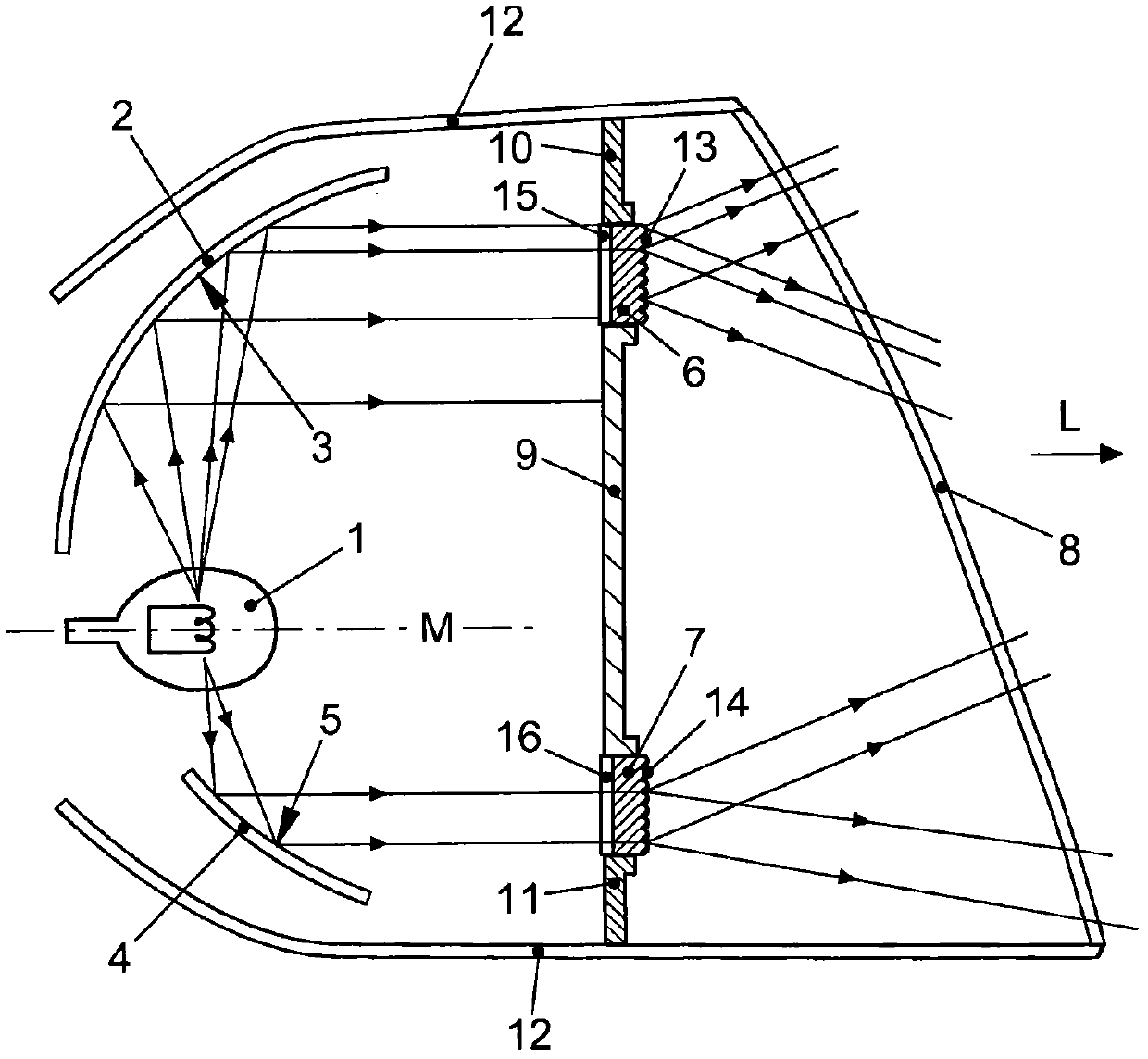
[0023] refer to figure 1 , first describe the basic structure of the lamp. The lights of the illustrated embodiment are tail lights. To clarify, figure 1 The cross-sections shown are not necessarily along a plane. Instead, the section can be chosen such that both mirrors are visible. In the following, orientation specifications such as horizontal, vertical and lateral relate to the installation of the lamp in the vehicle.

[0024] The lamp comprises a light source 1 . Here, the light source is a light source 1 known per se, which is as point-shaped as possible. Furthermore, a first mirror 2 with a mirror surface 3 is provided. Such as figure 1 As shown, the light emitted by the light source 1 hits the reflector surface 3 and reflects there in direction L the substantial light radiation of the lamp. The mirror surface 3 is located on the surface of the first paraboloid of revolution, where the light source 1 is arranged at the focus of the first paraboloid of revolution...


PUM


Abstract

The present invention relates to a lamp for a vehicle having a light source (1), a first reflector (2), and at least one light pane (6, 7), which are disposed so that light emitted by the light source (1) is reflected by a reflector face (3) of the first reflector (2) and forms a first lamp face (17) of the lamp. The lamp according to the invention is characterized in that the lamp has at least one second reflector (4), the reflector face (5) thereof being disposed separately from the reflector face (3) of the first reflector (2) and the second reflector being disposed so that light emitted by the light source (1) is reflected by the reflector face (5) of the second reflector (4) and forms a second lamp face (18) of the lamp, wherein said first and said second lamp faces (17, 18) are not coherent.

Description

technical field [0001] The invention relates to a lamp for vehicles, comprising a light source, a first reflector and at least one reflector glass arranged in such a way that the light emitted by the light source is reflected by a reflector surface of the first reflector and forms a first luminous surface of the lamp. Background technique [0002] The problem arises in new vehicle designs that, because of the desired aerodynamics and the desired design, the installation space available for the lighting unit, in particular for the lights including the taillights and the headlights, is very limited. However, the signaling effect of the lamp is determined by the perimeter dimensions and the brightness of the light exit surface. In addition, lights play an important role in vehicle design. Through the design of the lights, the vehicle is often given a characteristic appearance that is easily recognizable. Moreover, the following problems arise, and the manufacturing cost of th...

Claims


Application Information

Patent Timeline
IPC IPC(8): F21V7/00F21V5/00F21V13/00F21W107/10
CPCF21S48/23F21S48/24F21S48/2212F21S43/26F21S43/30F21S43/40
Inventor H·基尔M·塔姆S·黑林
Owner VOLKSWAGEN AG
Why Eureka
Try Eureka