Converter control method

A control method and converter technology, applied in current controller, AC motor control, control system, etc., can solve the problems of integrator action interference, DC voltage overshoot, etc., achieve stable transient response, suppress size, improve The effect of power factor

Active Publication Date: 2011-04-06
DAIKIN IND LTD
View PDF9 Cites 5 Cited by
  • Summary
  • Abstract
  • Description
  • Claims
  • Application Information

AI Technical Summary

Problems solved by technology

Therefore, as will be described later as a comparative example with respect to the embodiment of the present invention, when recovering from an instantaneous voltage drop, the operations of the above two integrators interfere, and there is a problem that an overshoot of the DC voltage occurs.

Method used


Image

  • Converter control method
  • Converter control method
  • Converter control method

Examples


Embodiment Construction

[0042] In the following, the same notation is used for the current itself as well as for the value of this current, as is often done in this field. For example, the expression "current I" can be used both when referring to the current I flowing through the circuit and when referring to its value. The same applies to voltage and other quantities.

[0043] A: overall structure

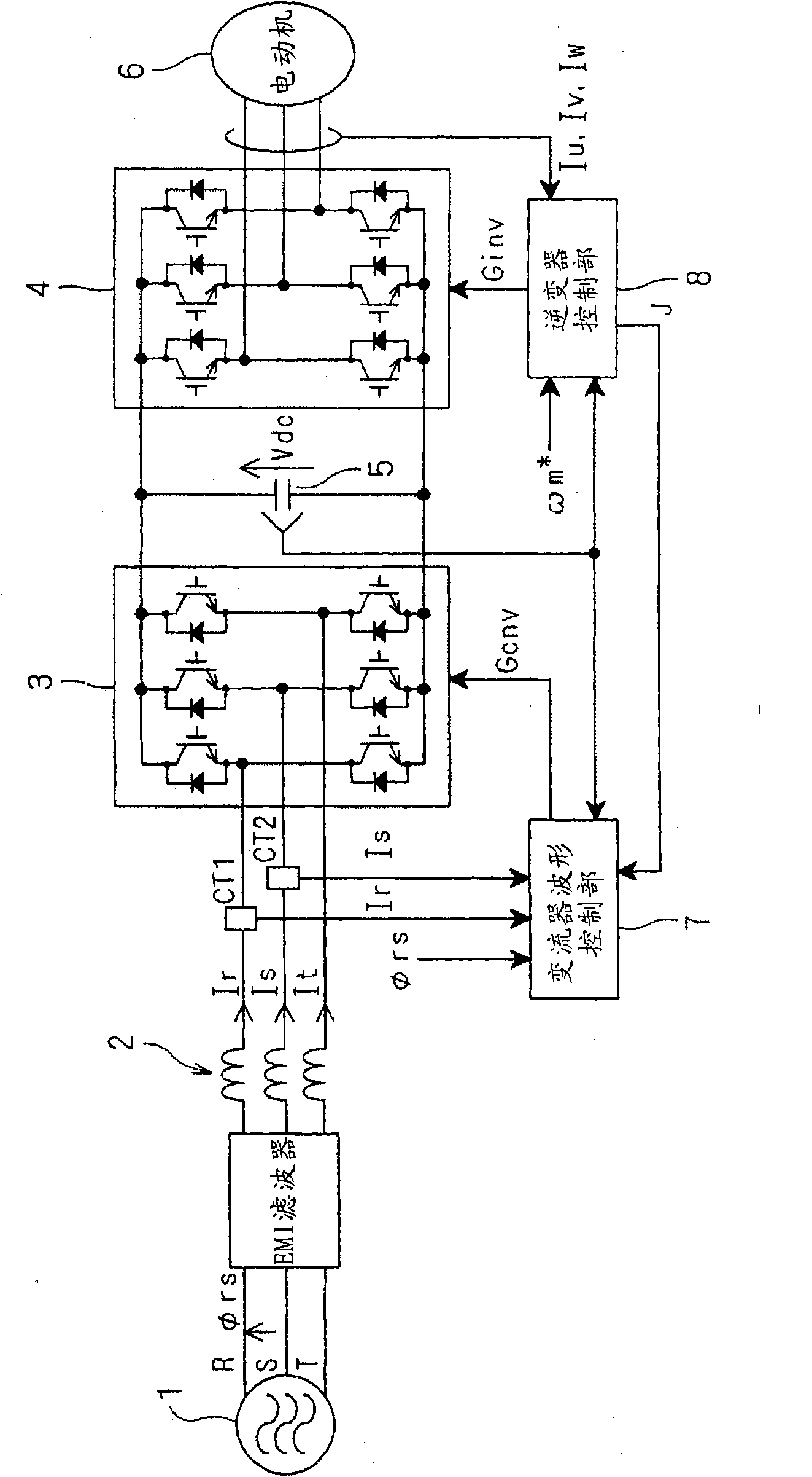
[0044] figure 1 It is a circuit diagram showing a converter to which a converter control method according to an embodiment of the present invention is applied and a structure connected thereto.

[0045] The multi-phase power supply 1 is a three-phase power supply that outputs three-phase voltages of R, S, and T phases. Although the number of phases in this embodiment is three, the number of phases is not limited to three.

[0046] The converter 3 inputs currents Ir, Is, It from the multi-phase power supply 1 through the EMI (Electro Magnetic Interference, electromagnetic interference) filter and the ...


PUM


Abstract

It is possible to control a DC voltage in accordance with fluctuation of a power source voltage without requiring detection of an effective power source voltage value. A PI control unit (702) performs PI control for a difference (deltaVdc) between a DC voltage instruction (Vdc*) and a DC voltage (Vdc) and outputs a d-axis current instruction value (Id*). A PI control unit (704) performs PI control for a difference (deltaId) between a d-axis current instruction value (Id*) and a d-axis current (Id) and outputs a d-axis voltage instruction value (Vd*). A PWM control unit (709) outputs a switching control signal (G1) which controls a converter switching operation according to the d-axis voltage instruction value (Vd*) and a q-axis voltage instruction value (Vq*). A DC voltage instruction (Vdc*) is generated by a voltage instruction calculation unit (710) according to the d-axis voltage instruction value (Vd*).

Description

technical field [0001] The invention relates to a method for controlling a converter, in particular to a method for controlling a converter for rectifying multi-phase current. Background technique [0002] A higher power factor is preferred when rectifying current drawn from an AC source to obtain a DC voltage. For example, in order to make the power factor 1 when using a voltage source PWM converter, it is necessary to set the output DC voltage to a value higher than the peak value of the output voltage of the AC power supply. Therefore, when the specification of the output voltage of the AC power supply actually used is unclear, the DC voltage is set to a voltage higher than the voltage of the general specification. [0003] However, increasing the set value of the DC voltage output from the converter increases the maximum value of the voltage value applied to the inverter device that receives the DC voltage. This will increase the loss of the switching elements of the c...

Claims


Application Information

Patent Timeline
Patent Type & Authority Applications(China)
IPC IPC(8): H02M5/458H02M7/219H02P21/00H02M7/12H02M7/48H02P6/06H02P6/08H02P6/182H02P6/28H02P21/22H02P27/08
CPCY02B70/126H02M7/219H02M1/4233H02P21/0003H02M2007/53876Y02B70/10H02M7/53876H02P2201/03H02M7/53
Inventor 川嶋玲二
Owner DAIKIN IND LTD
Why Eureka
Try Eureka