
Full-automatic paper holding machine

A paper support machine, fully automatic technology, applied in the direction of object separation, object supply, pile separation, etc., can solve the problems of paper support being difficult to separate, high error rate, low efficiency, etc., to achieve the effect of full automation, coherent and fast action

Inactive Publication Date: 2011-04-13
施鸿雄
View PDF4 Cites 2 Cited by
  • Summary
  • Abstract
  • Description
  • Claims
  • Application Information

AI Technical Summary

Problems solved by technology

[0002] At present, in the field of paper tray placement technology for cakes and other foods, there are mainly two ways: traditional manual placement and mechanical placement. Traditional manual placement of paper trays has always been a heavy manual labor, which not only requires certain labor costs, but also requires It takes a lot of time; and the paper tray machines that appear on the market now mainly use vacuum suction cups to pick up the paper tray and put it to a fixed position
However, because the stacked paper holders made by stamping are extremely thin, the paper holders are not easy to separate due to the air pressure. The paper holders need to be peeled off one by one, and then sucked up with a suction cup and placed in a fixed position. , therefore, the entire adsorption mechanism is either very cumbersome, inefficient, or has a high error rate

Method used


Image

  • Full-automatic paper holding machine
  • Full-automatic paper holding machine
  • Full-automatic paper holding machine

Examples


Embodiment 1

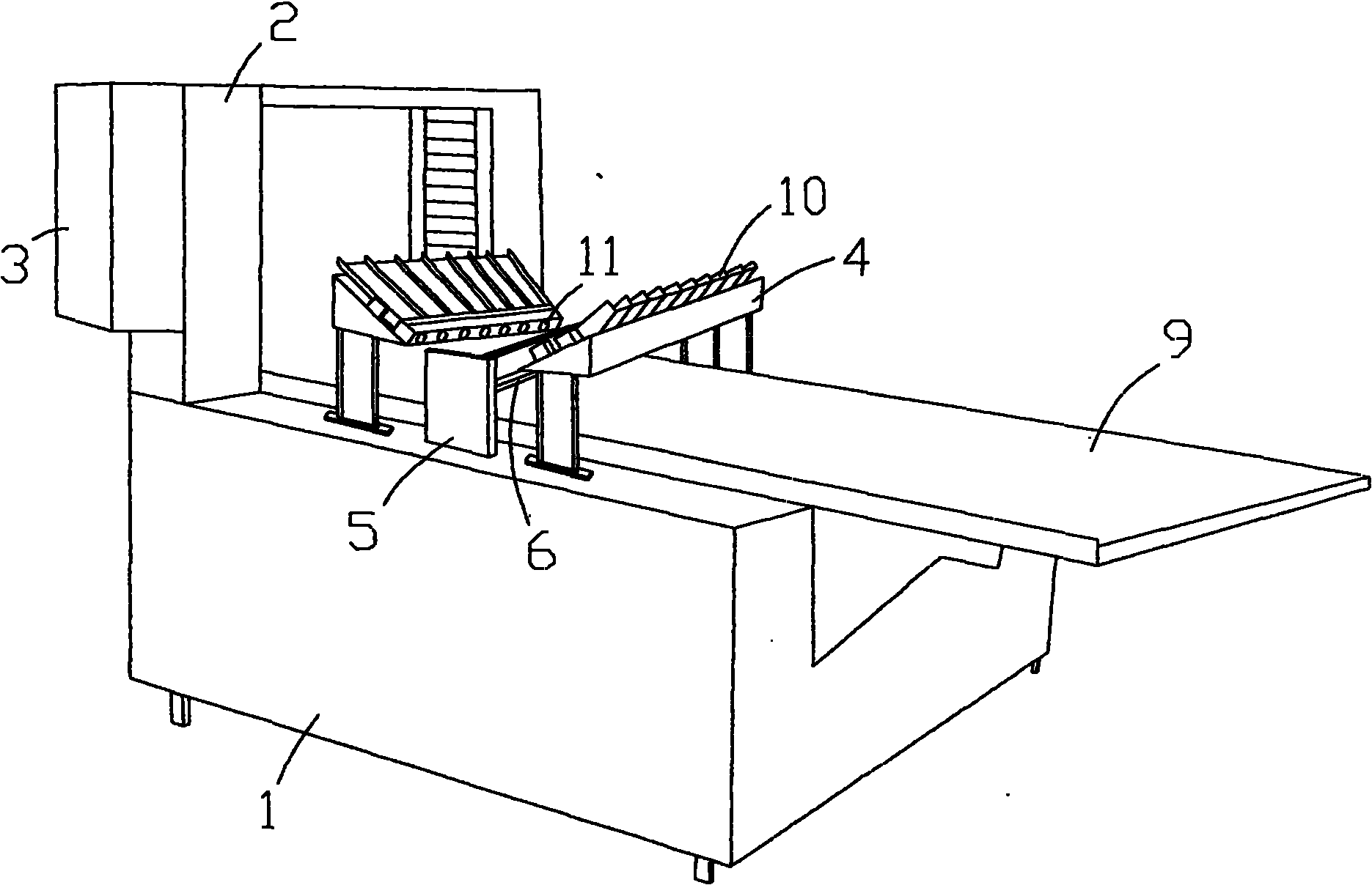
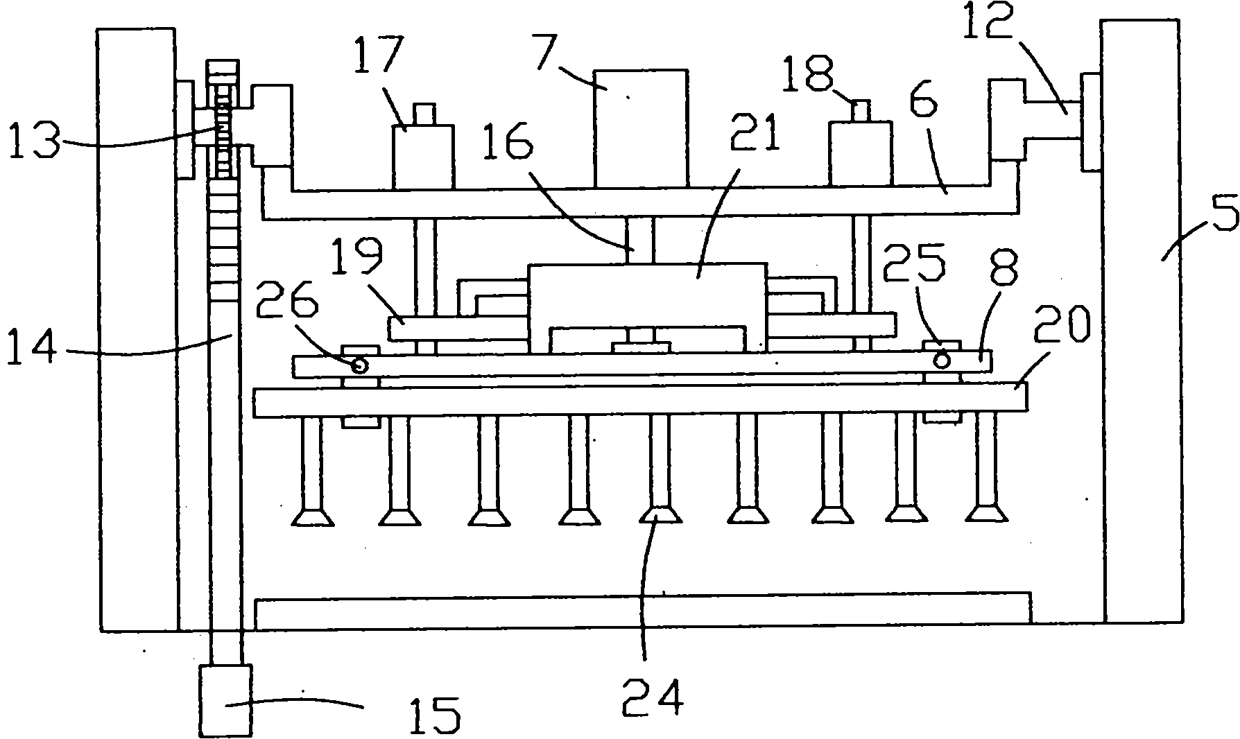
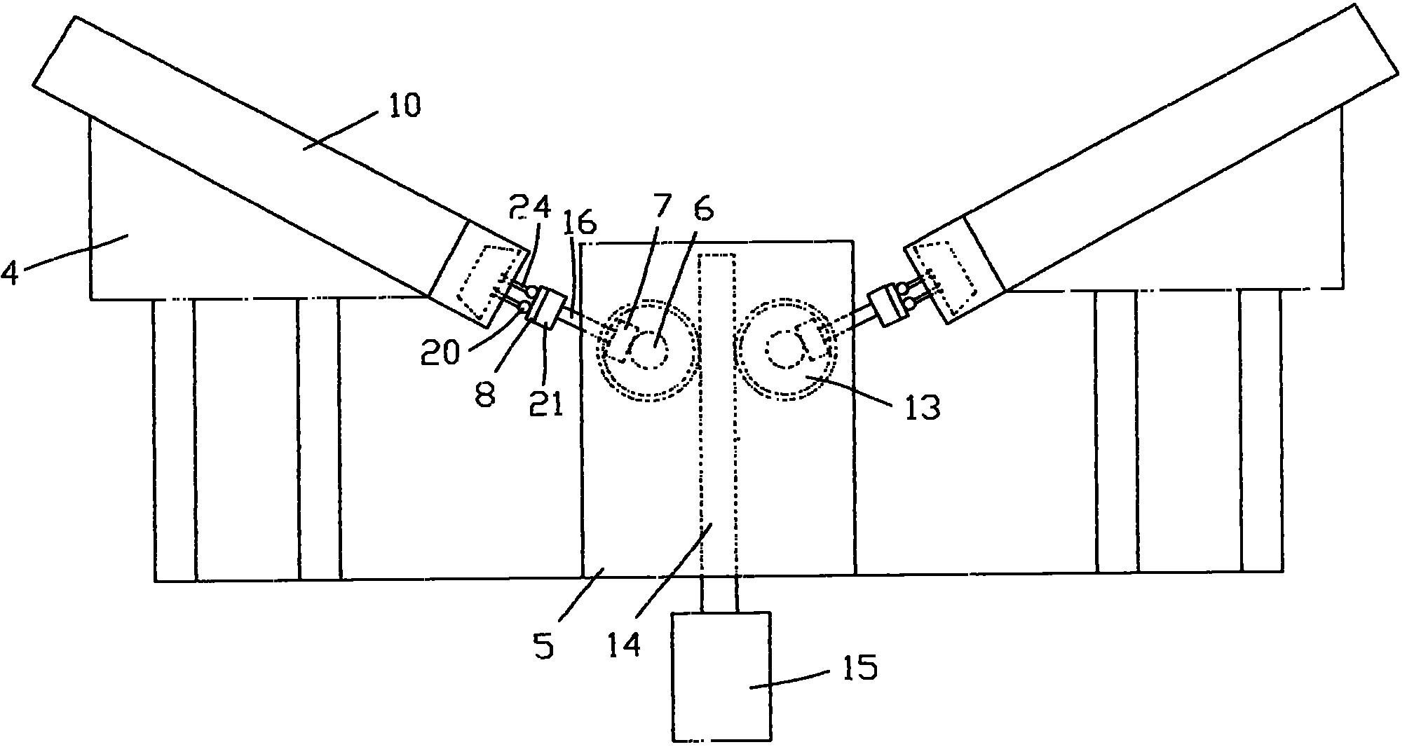
[0022] Embodiment 1, with reference to Figure 1~6 As shown, a fully automatic paper tray machine includes a base 1, a baking tray rack 2, a control box 3, a paper bracket 4, a bracket 5, a beam 6, a lifting cylinder 7, and a mounting plate 8. Conveyor belt 9 is arranged above, and grill frame 2 is welded on one end of machine base 1, and a side of grill frame 2 is provided with control box 3, is used for the action control of whole machine. Both the paper bracket 4 and the support 5 are arranged at the upper middle position of the base 1, wherein the number of the paper bracket 4 is 2 and symmetrically arranged on both sides of the bracket 5, and the bracket 5 is arranged on both sides of the base 1 . The upper end of the paper holder 4 is designed as a triangle, and the included angle between the hypotenuse of the triangle and the horizontal direction is between 35° and 45°. On the inclined surface of the upper end of the paper holder 4, there are at least one paper holder...

Embodiment 2

[0027] Embodiment 2, with reference to Figure 7 As shown, this embodiment is a further improvement of the above-mentioned embodiment 1. The clamping cylinder 21 is directly connected to the lifting cylinder 7 through the suspension rod 16, and the clamping cylinder 21 and the beam 6 are perpendicular to each other. Both ends are provided with clamping guide rods 23 , the bottom ends of the clamping guide rods 23 are fixed on the clamping plate 19 , and the air pipe 20 is fixedly connected directly under the clamping plate 19 . In this way, the mounting plate 8, the chute 22, the clamping slide seat 25 and the clamping slide bar 26 can be directly omitted. Compared with the above-mentioned embodiment 1, this embodiment has the characteristics of simpler structure and higher efficiency.


PUM


Abstract

The invention relates to a full-automatic paper holding machine relating to the technical field of food machinery. The full-automatic paper holding machine comprises a machine base, a comal rack, a control box, paper holders, brackets, beams, lifting cylinders and mounting plates, wherein a conveyer belt is arranged on the machine base, the comal rack is arranged on one end of the machine base, and the control box is arranged at one side of the comal rack. The full-automatic paper holding machine is characterized in that the brackets are respectively arranged at both sides on the machine base, two mutually parallel rotatable beams are arranged between the brackets, each beam is provided with a lifting cylinder, a mounting plate is arranged below each lifting cylinder, a sucker is arranged below each mounting plate, and the paper holders are respectively arranged at both sides of the brackets. The invention has the advantages that the suckers are controlled by the lifting cylinders to move in a vertical direction and controlled by the machine base to move oppositely so that the two corresponding suckers are clamped and released; by utilizing a turnover gas cylinder, the suckers circumferentially move, and paper trays are arranged in a preset position from the paper holder, and the action is coherent, rapid and accurate and has high efficiency.

Description

technical field [0001] The invention relates to the technical field of food machinery, in particular to a fully automatic paper tray machine. Background technique [0002] At present, in the field of paper tray placement technology for cakes and other foods, there are mainly two ways: traditional manual placement and mechanical placement. Traditional manual placement of paper trays has always been a heavy manual labor, which not only requires certain labor costs, but also needs It takes a lot of time; and the paper holder machines that appear on the market now mainly use vacuum suction cups to pick up the paper holder and put it to a fixed position. However, because the stacked paper holders made by stamping are extremely thin, the paper holders are not easy to separate due to the air pressure. The paper holders need to be peeled off one by one, and then sucked up with a suction cup and placed in a fixed position. , therefore, the entire adsorption mechanism is either very ...

Claims


Application Information

Patent Timeline
Patent Type & Authority Applications(China)
IPC IPC(8): A21B5/02B65H3/08B65H5/00
Inventor 施鸿雄
Owner 施鸿雄
Learn More