Spring feeding device, spring loading device and method for assembling optical fiber connector

An optical fiber connector and equipment technology, applied in the field of spring feeding devices, can solve the problem that the spring is easily stuck at the connection between the transparent tube and the optical fiber core, affects the performance and service life of the optical fiber connector, and the processing accuracy of the transparent tube and the optical fiber core is not enough. and other problems, to achieve the effect of reasonable and ingenious structural design, shortening of working hours and cost saving

Active Publication Date: 2021-03-05
深圳市富盈源科技有限公司
View PDF3 Cites 0 Cited by
  • Summary
  • Abstract
  • Description
  • Claims
  • Application Information

AI Technical Summary

Problems solved by technology

[0003] Among them, the quality and dimensional accuracy of the spring have a great influence on the performance of the optical fiber connector. In the existing automatic assembly line of the optical fiber connector, when the spring is put on the transparent tube, the spring is easy to shift; and because the transparent tube and the optical fiber core The processing accuracy is not enough, when the spring is set, the spring is easy to get stuck at the connection between the transparent tube and the optical fiber core, which seriously affects the performance and service life of the optical fiber connector

Method used


Image

  • Spring feeding device, spring loading device and method for assembling optical fiber connector
  • Spring feeding device, spring loading device and method for assembling optical fiber connector
  • Spring feeding device, spring loading device and method for assembling optical fiber connector

Examples


Embodiment Construction

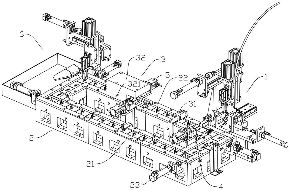
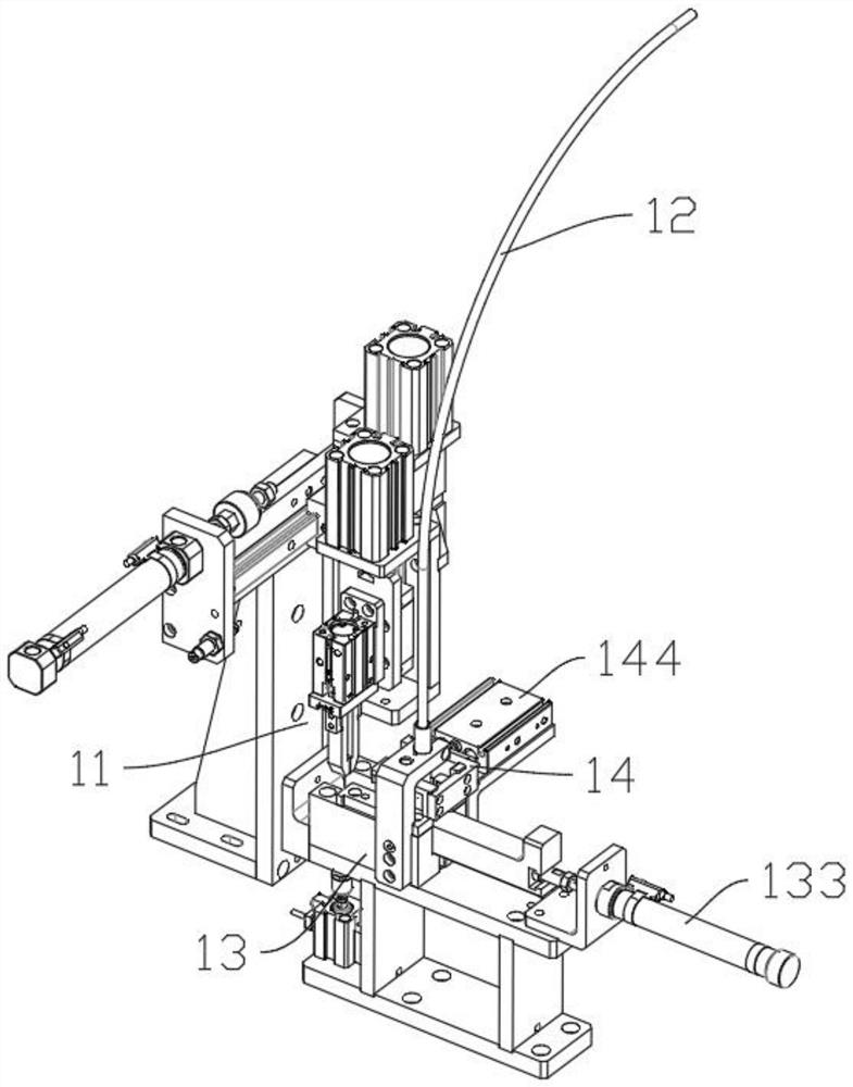
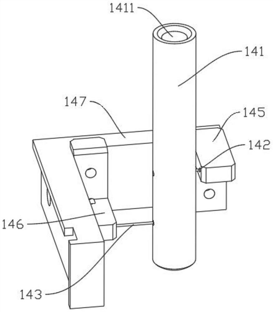
[0031] Examples, see Figure 1 to Figure 5, a spring feeding device 1 for optical fiber connector assembly provided in this embodiment includes a first handling manipulator 11, a spring feeding tube 12, a spring displacement mechanism 13 and an output device arranged on the spring feeding tube 12. The distributing mechanism 14 at the end, the first handling manipulator 11 is arranged on one side of the spring feeding pipe 12, the distributing mechanism 14 includes a distributing cylinder 141 and an upper distributing needle 142 and a lower distributing needle 143 arranged horizontally A material distribution through hole 1411 is provided through the upper and lower end surfaces of the material distribution cylinder 141, and the upper material distribution needle 142 and the lower material distribution needle 143 are inserted into the material distribution cylinder 141 corresponding to the material distribution through hole 1411, A distributing needle driving mechanism for driv...


PUM


Abstract

The invention discloses a spring feeding device used for assembling optical fiber connectors, which comprises a first handling manipulator, a spring feeding pipe, a spring displacement mechanism and a material distributing mechanism arranged at the output end of the spring feeding pipe. The manipulator is set on one side of the spring feeding tube. The material distribution mechanism includes the material distribution cylinder and the upper and lower distribution needles arranged horizontally. The distributing needles correspond to the distributing through holes and are interspersed on the distributing cylinder. A distributing needle driving mechanism is provided on one side of the distributing cylinder for driving the upper distributing needle and the lower distributing needle to move laterally. The spring displacement mechanism corresponds to the first The output end setting of the handling manipulator and the distribution cylinder. The invention also discloses a spring loading device and method for assembling the optical fiber connector. The structure design of the present invention is reasonable and ingenious. Through the spring feeding device and the spring detection device, the spring is sequentially loaded and the spring installation is detected, and the spring is automatically installed while ensuring the installation quality of the spring.

Description

technical field [0001] The invention relates to the assembly of optical fiber connectors, in particular to a spring feeding device, spring loading equipment and method for assembling optical fiber connectors. Background technique [0002] Usually, an LC fiber optic connector includes a front shell, an optical fiber core, a transparent tube, a spring, and a rear shell. Put a spring on the transparent tube, and finally use the back shell to squeeze the spring to buckle on the front shell. [0003] Among them, the quality and dimensional accuracy of the spring have a great influence on the performance of the optical fiber connector. In the existing automatic assembly line of the optical fiber connector, when the spring is put on the transparent tube, the spring is easy to shift; and because the transparent tube and the optical fiber core The processing accuracy is not enough, when the spring is set, the spring is easy to get stuck at the connection between the transparent tube...

Claims


Application Information

Patent Timeline
Patent Type & Authority Patents(China)
IPC IPC(8): B23P19/00
Inventor 廖晓蓓
Owner 深圳市富盈源科技有限公司
Why Eureka
Try Eureka