
Fin cutting machine for plate-fin heat exchanger

A plate-fin heat exchanger and cutting machine technology, which is applied in metal processing and other directions, can solve the problems of high elasticity, low efficiency, and the inability of the cutting machine to cut, and achieve the effect of high quality and coherent and fast cutting action

Inactive Publication Date: 2011-04-13
张舜德 +1
View PDF5 Cites 11 Cited by
  • Summary
  • Abstract
  • Description
  • Claims
  • Application Information

AI Technical Summary

Problems solved by technology

The existing aluminum fin forming machine usually has a structure, mainly including a feeding mechanism for conveying aluminum foil, and a forming mechanism for wave forming. In the production of plate-fin heat exchanger fins, due to the shape of the fins (The shape of the fins is divided into straight, staggered teeth and corrugated) and characteristics (the material is aluminum foil with low strength and large elasticity between pitches) determines that general cutting machines cannot be cut
Therefore, the previous fin cutting was done manually, which has low efficiency, large errors and many waste products.

Method used


Image

  • Fin cutting machine for plate-fin heat exchanger
  • Fin cutting machine for plate-fin heat exchanger
  • Fin cutting machine for plate-fin heat exchanger

Examples


Embodiment Construction

[0021] The present invention will be further described in detail below in conjunction with the accompanying drawings and embodiments.

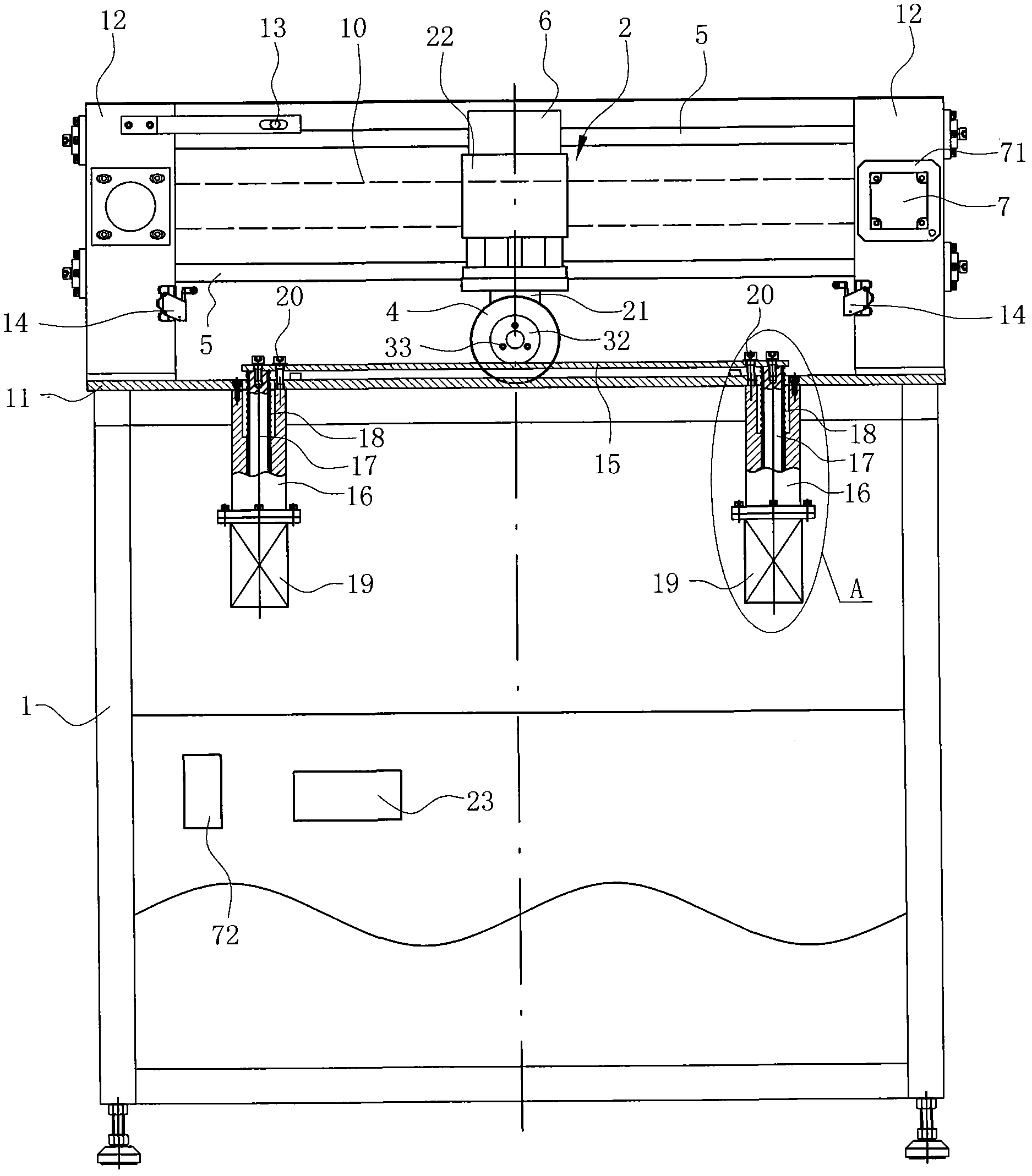
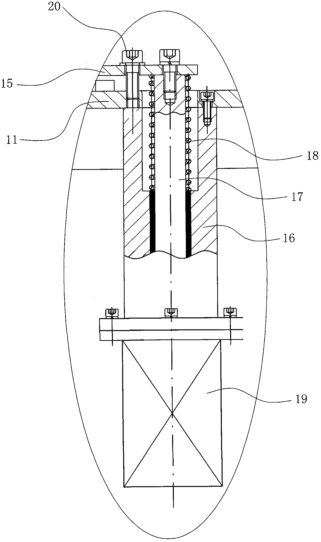
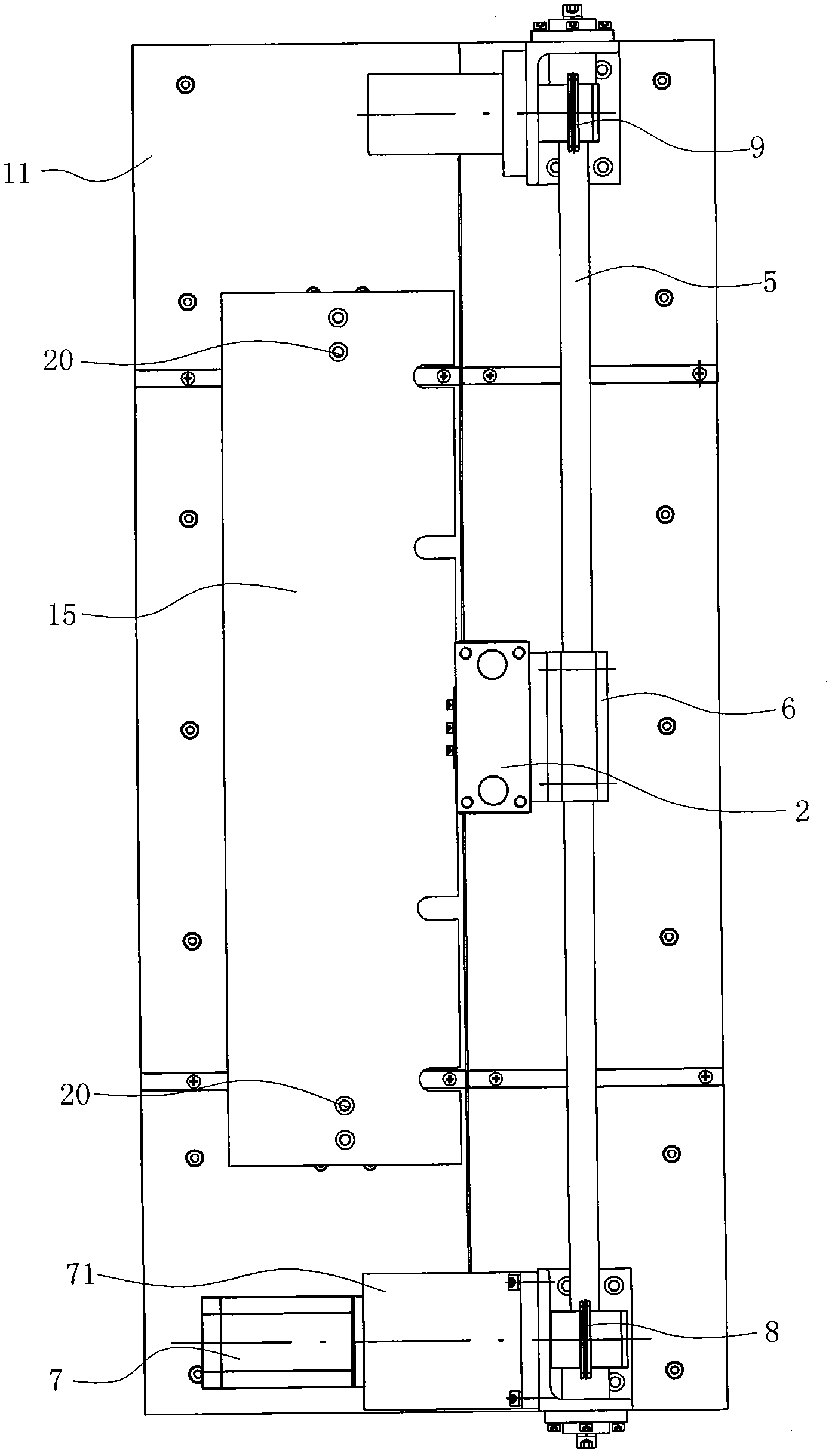
[0022] Such as Figure 1-5 Shown is a preferred embodiment of the present invention.

[0023] A fin cutting machine for a plate-fin heat exchanger, including

[0024] The support 1 having a fin cutting platform 11 is fixed with two parallel and spaced installation seats 12 on the fin cutting platform 11, and the installation seats 12 are in the shape of a cuboid.

[0025] The cutting device for cutting the fins includes a cylinder 2, a knife seat 3 and a cutting blade 4; the knife seat 3 is installed on the piston rod 21 of the cylinder through a one-way bearing 31 so that it can be unidirectional around its own axis relative to the piston rod 21. Rotate, the axis of knife seat 3 is perpendicular to the moving direction of piston rod 21; Cutting blade 4 is a disc-shaped blade, and cutting blade 4 is pressed on the knife seat 3 by front press...


PUM


Abstract

The invention relates to a fin cutting machine for a plate-fin heat exchanger, which is characterized by comprising a bracket, a cutting device, a cutting guide device, a cutting power device and a pressing device, wherein the bracket is provided with a fin cutting platform; the cutting device is used for cutting fins, and comprises a cylinder, a tool post and a cutting blade; the tool post is fixed on a piston rod of the cylinder; the cutting blade is arranged on the tool post; the cutting guide device comprises guide rods fixed on the bracket; the cylinder is arranged on the guide rods and can slide leftwards and rightwards along the guide rods; the cutting power device is arranged on the bracket, and is used for driving the cylinder to slide leftwards and rightwards along the guide rods; and the pressing device is arranged on the fin cutting platform, and is used for pressing the fins in the cutting process of the cutting blade to prevent the fins from moving forwards. The fin cutting machine is particularly suitable for cutting the fins of the plate-fin heat exchanger, and can cut the fins more efficiently and accurately.

Description

technical field [0001] The invention relates to a cutting device, in particular to a fin cutting machine for a plate-fin heat exchanger. Background technique [0002] Aluminum fins are widely used in automotive aluminum water tank radiators, parallel flow condensers, parallel flow evaporators, radiators or surface coolers, variable air volume air conditioning cabinets, fan coils and heat exchangers. The main function of the component is to dissipate heat. The existing aluminum fin forming machine usually has a structure, mainly including a feeding mechanism for conveying aluminum foil, and a forming mechanism for wave forming. In the production of plate-fin heat exchanger fins, due to the shape of the fins (The shape of the fins is divided into straight, staggered teeth and corrugated) and the characteristics (the material is aluminum foil with low strength and large elasticity between pitches) determine that general cutting machines cannot be cut. Therefore, the previous ...

Claims


Application Information

Patent Timeline
Patent Type & Authority Applications(China)
IPC IPC(8): B26D1/14B26D5/08B26D7/26B26D7/01
Inventor 张舜德王荣
Owner 张舜德
Learn More