Powder feeding device

A feeding device and powder technology, which is applied in the field of machinery, can solve the problems of discontinuous feeding, easy bonding of blades, unstable feeding device, etc., and achieve the effect of reducing the possibility and smooth feeding

Inactive Publication Date: 2011-04-13
SANY HEAVY IND CO LTD (CN)
View PDF4 Cites 1 Cited by
  • Summary
  • Abstract
  • Description
  • Claims
  • Application Information

AI Technical Summary

Problems solved by technology

[0003] The purpose of the present invention is to provide a powder feeding device to solve the problem that the square tube section above the feeding device is too narrow and easy to arch, resulting in discontinuous and unobstructed feeding, and the blades are easy to stick to the powder, which leads to the instability of the feeding device. The problem

Method used


Image

  • Powder feeding device
  • Powder feeding device
  • Powder feeding device

Examples


Embodiment Construction

[0016] It should be noted that, in the case of no conflict, the embodiments in the present application and the features in the embodiments can be combined with each other. The present invention will be described in detail below with reference to the accompanying drawings and examples.

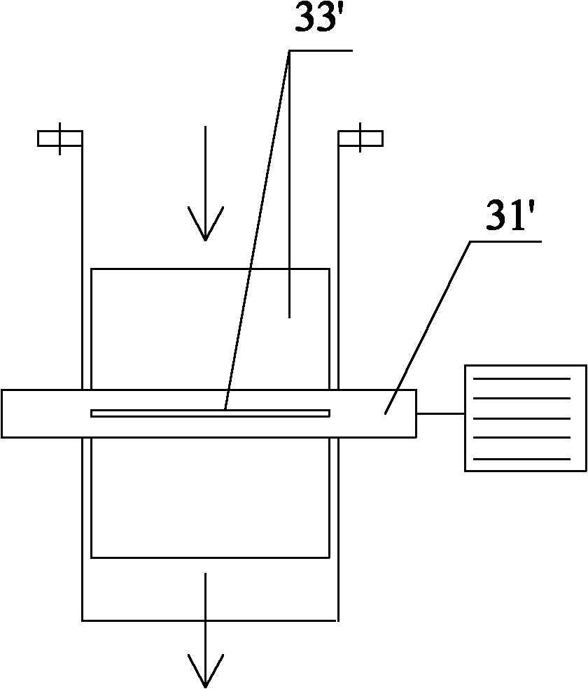
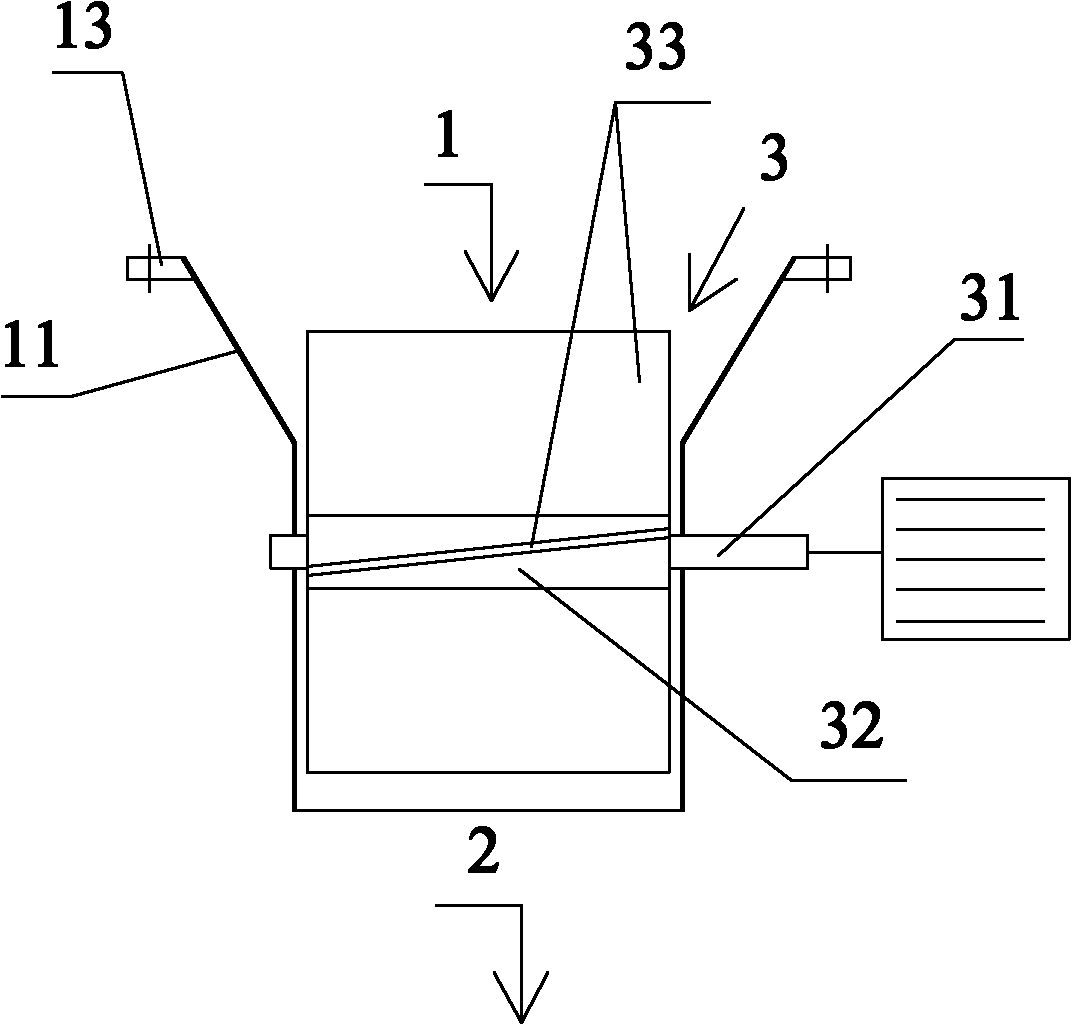
[0017] figure 2 A schematic structural view of the powder feeding device according to the present invention is shown. Such as figure 2 As shown, the powder feeding device includes: a housing with an inlet 1 and an outlet 2, an impeller 3 arranged in the housing, and a driving device for driving the impeller. In this embodiment, the driving device uses a motor to reduce the speed All-in-one machine. The casing includes a funnel part 11 , the impeller 3 is located at the lower part of the funnel part 11 , and the blades 33 of the impeller 3 at least partly extend upwards into the inclined discharge area of ​​the funnel part 11 . The funnel makes it difficult for the powder to arch when feed...


PUM


Abstract

The invention provides a powder feeding deice which comprises a housing with a feed port and a discharge port, an impeller arranged in the housing and a driving device for driving the impeller, wherein the housing comprises a funnel part, the impeller is positioned at the lower part of the funnel part, and at least part of blades of the impeller extend upwards till extending into an inclined baiting region of the funnel part. The problem of discontinuous and unobstructed baiting because a square cylinder section on the feeding device is easy to arch due to being too narrow can be solved by using the power feeding device.

Description

technical field [0001] The invention relates to the field of machinery, in particular to a powder feeding device. Background technique [0002] The general scheme adopted by the powder feeding device is to arrange regular blades on a shaft to form a simple device to convey powder to the scale body of the weighing device, such as figure 1 shown. The device is provided with a horizontal shaft 31' in a square cylindrical shell, and several blades 33' are evenly arranged along the radial direction of the shaft. The blades are parallel to the axial direction, and the shaft is driven by external power. The device is placed in the lower part of the powder bin, and feeds the weighing device through the rotation of the impeller. However, there are such problems in the above-mentioned device. First, the square tube section above the feeding device is too narrow and easy to arch. At this time, the feeding is not easy to be continuous and smooth; second, the blades of the feeding devi...

Claims


Application Information

Patent Timeline
Patent Type & Authority Applications(China)
IPC IPC(8): B65G33/14B65G33/26B65G33/34B65G33/24
Inventor 丁少伟
Owner SANY HEAVY IND CO LTD (CN)
Why Eureka
Try Eureka