Check patentability & draft patents in minutes with Patsnap Eureka AI!

Floor and connection structure thereof

A technology for connecting structures and floors, applied in the field of building decoration materials, can solve the problems of high manufacturing cost and inconvenient assembly, and achieve the effects of low manufacturing cost, convenient assembly and reliable connection

Inactive Publication Date: 2014-03-12
杭州暖捷环境科技有限公司
View PDF5 Cites 0 Cited by
  • Summary
  • Abstract
  • Description
  • Claims
  • Application Information

AI Technical Summary

Problems solved by technology

[0003] The purpose of the present invention is to provide a floor connection structure and floor with low manufacturing cost, convenient assembly and reliable connection, which solves the problems of high manufacturing cost and inconvenient assembly in the prior art

Method used


Image

  • Floor and connection structure thereof
  • Floor and connection structure thereof
  • Floor and connection structure thereof

Examples


Embodiment 1

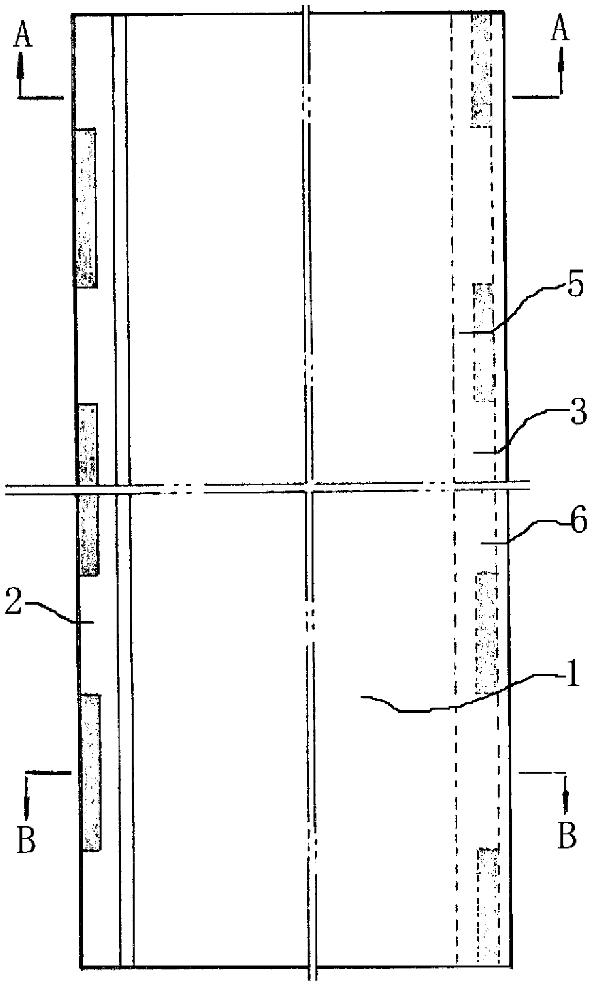
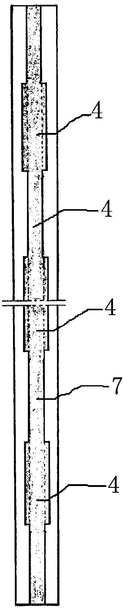
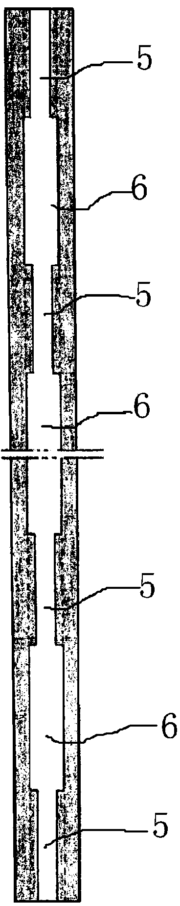
[0028] Embodiment 1: as figure 1 , figure 2 , image 3 , Figure 4 and Figure 5 As shown, the floor includes a floor body 1, the floor body 1 includes opposite first sides 2 and second sides 3, the first side 2 is formed with a plurality of tenons 4 arranged at equal intervals, and the tenons 4 include clamping parts 41 and Connected to the connection part 42 between the card part 41 and the floor body 1, the thickness of the card part 41 is greater than the thickness of the connection part 42, and the upper side and the lower side of the card part 41 are respectively formed with upper convex bodies that protrude upward or downward 411 and the lower convex body 412, there is a transition part 7 connecting two adjacent tenons 4 between adjacent tenons 4, the thickness of the transition part 7 is equal to the thickness of the tenon connection part 42; the second side 3 is formed with multiple Tenon grooves 5 arranged at equal intervals and matched with the tenon 4, the ten...

Embodiment 2

[0031] Embodiment 2: as Figure 9 , Figure 10 , Figure 11 , Figure 12 and Figure 13 As shown, the floor includes a floor body 1, the floor body 1 includes opposite first sides 2 and second sides 3, the first side 2 is formed with a plurality of tenons 4 arranged at equal intervals, and the tenons 4 include clamping parts 41 and Connected to the connecting part 42 between the card part 41 and the floor body 1, the thickness of the card part 41 is greater than the thickness of the connecting part 42, and the upper side of the card part 41 is formed with an upwardly protruding upper convex body 411. The transition portion 7 where two adjacent tenons 4 are connected together, the thickness of the transition portion 7 is equal to the thickness of the tenon connection portion 42; the second side 3 is formed with a plurality of tenon grooves 5 arranged at equal intervals and matched with the tenon 4, the tenon The groove 5 includes a card groove 51 that cooperates with the cl...


PUM


Abstract

A floor joint structure and a floor therewith are provided. In which, the floor joint structure comprises a first floor (10) and an adjacent second floor (11), the side of the first floor (10) connecting to the second floor (11) is arranged with several tongues (4) at certain intervals, the tongue (4) includes a lock portion (41) and a connecting portion (42) connecting the lock portion (41) to the floor body, and the thickness of the lock portion (41) is larger than that of the connecting portion (42). The side of the second floor (11) connecting to the first floor (10) is arranged with several grooves (5) matched with the tongues at certain intervals, the groove (5) comprises a lock groove (51) matched with the lock portion (41) of the tongue (4) and a connecting groove (52) matched with the connecting portion (42) of the tongue (4), an opening groove (6) is set between the adjacent connecting grooves (52), the depth of the opening groove (6) is equal to that of the groove (5), and the thickness of the opening groove (6) is larger than the thickness of the lock portion (41) so that the whole tongue (4) can be inserted into the opening groove (6). The length of the opening groove (6) extending along the side of the second floor (11) is larger than that of the tongue (4) extending along the side of the first floor (10).

Description

technical field [0001] The invention relates to a floor connection structure and a floor, belonging to the technical field of building decoration materials. Background technique [0002] In the prior art, the connection between adjacent floors is often achieved by connecting pieces independent of the floor, such as a floor board (patent number: CN200710000711.9), which is rectangular and has a first opposite side and a second opposite side The adjacent floor boards are installed through the floor connectors to form a floor; the floor boards are provided with a first groove on at least the first opposite side to cooperate with the floor connectors. In the above technical solution, an additional connecting piece needs to be configured, and the manufacturing cost is relatively high, and the assembly is inconvenient. Contents of the invention [0003] The object of the present invention is to provide a floor connection structure and floor with low manufacturing cost, convenie...

Claims


Application Information

Patent Timeline
Patent Type & Authority Patents(China)
IPC IPC(8): E04F15/02
CPCE04F2201/0123E04F15/02
Inventor 李增清
Owner 杭州暖捷环境科技有限公司
Features
  • R&D
  • Intellectual Property
  • Life Sciences
  • Materials
  • Tech Scout
  • Unparalleled Data Quality
  • Higher Quality Content
  • 60% Fewer Hallucinations
Learn More