
Transmission mechanism of multifunctional testing equipment for ignition lock

A multi-functional testing and transmission mechanism technology, applied in the direction of mechanical equipment, transmission devices, friction transmission devices, etc., can solve the problems of only longitudinal reciprocating movement, labor-intensive, time-consuming, etc., and achieve long-term stable use

Inactive Publication Date: 2012-09-26
苏州拓思达自动化设备有限公司
View PDF4 Cites 0 Cited by
  • Summary
  • Abstract
  • Description
  • Claims
  • Application Information

AI Technical Summary

Problems solved by technology

[0002] Ignition lock test equipment in the prior art, especially ignition lock test equipment for automobiles, tanks, motorcycles, aviation, and navigation, such as ignition locks, seesaws, various types of switches, etc., needs repeated actions To test its performance, the transmission mechanism of the prior art is to make the test transmission shaft only reciprocate, or only reciprocate longitudinally. This kind of test equipment cannot meet the test technical requirements of reciprocating rotation and longitudinal reciprocating movement at the same time, which is time-consuming. labor-intensive

Method used


Image

  • Transmission mechanism of multifunctional testing equipment for ignition lock
  • Transmission mechanism of multifunctional testing equipment for ignition lock
  • Transmission mechanism of multifunctional testing equipment for ignition lock

Examples


Embodiment

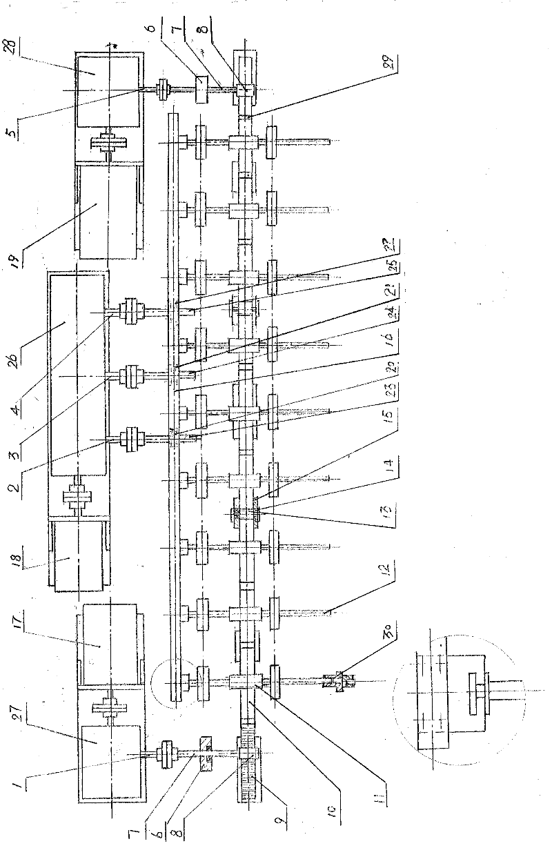
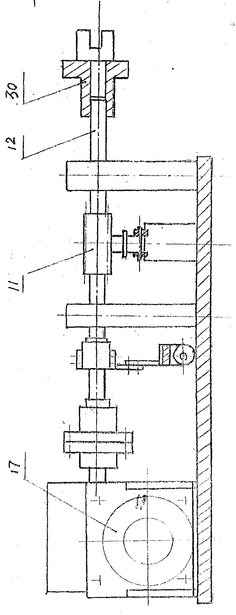
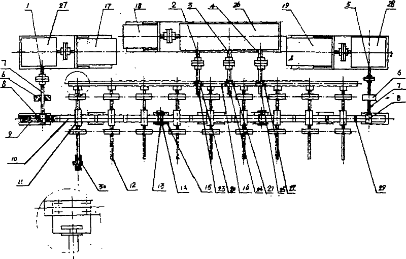
[0011] Example: see attached figure 1 to attach figure 2 , the transmission mechanism of the multifunctional ignition lock testing equipment, it comprises the first stepping motor 17 and the 3rd stepping motor 19, the first reduction box 27 that is connected with the output shaft of the first stepping motor 17, and the The third reduction box 28 connected to the output shaft of the third stepping motor 19 is in phase with the first output shaft 1 on the first reduction box 27 and the fifth output shaft 5 on the third reduction box 28. Connected gear shaft 7, the gear 8 that is arranged on the gear shaft 7, the second stepping motor 18, the three output shaft reduction box 26 that is connected with the output shaft of the second stepping motor 18, the three output shafts The first output shaft 2, the second output shaft 3, and the third output shaft 4 of the reduction box 26 are respectively connected with a first threaded screw mandrel 23, a second threaded screw mandrel 24,...


PUM


Abstract

The invention relates to a transmission mechanism of multifunctional testing equipment for an ignition lock. The transmission mechanism comprises a reduction box (27) of a first stepper motor (17), a reduction box (28) of a third stepper motor and a three-output shaft reduction box (26) of a second stepper motor (18), wherein output shafts of the three-output shaft reduction box (26) are connected with three threaded screw rods (23) (24) and (25); the three threaded screw rods (23) (24) and (25) are in threaded connection with three nuts (20) (21) and (22) on a longitudinal reciprocating lever (29); the longitudinal reciprocating lever (29) is connected with 9 to 12 testing transmission shafts (12); each testing transmission shaft (12) is connected with a gear (11); the gear (11) is meshed with a rack (10) on a transverse reciprocating lever (16); and a gear (8) on a gear shaft (17) is also meshed with the rack (10) on the transverse reciprocating lever (16). The 9 to 12 testing transmission shafts can be rotated at the same time in a reciprocating way and moved longitudinally. The head of each testing transmission shaft (12) is provided with an automatic protective device (30) ofa tested part. The transmission mechanism is suitable for testing equipment of various ignition lock electrical appliances of different models.

Description

technical field [0001] The patent of the present invention relates to the transmission mechanism of thousands of different types of ignition lock multifunctional testing equipment in aviation, navigation, transportation and military fields. Background technique [0002] Ignition lock test equipment in the prior art, especially ignition lock test equipment for automobiles, tanks, motorcycles, aviation, and navigation, such as ignition locks, seesaws, various types of switches, etc., needs repeated actions To test its performance, the transmission mechanism of the prior art is to make the test transmission shaft only reciprocate, or only reciprocate longitudinally. This kind of test equipment cannot meet the test technical requirements of reciprocating rotation and longitudinal reciprocating movement at the same time, which is time-consuming. And labor-intensive. Contents of the invention [0003] The object of the present invention is to provide a transmission mechanism of...

Claims


Application Information

Patent Timeline
IPC IPC(8): F16H37/00F16H25/20F16H19/04
Inventor 顾小清
Owner 苏州拓思达自动化设备有限公司
Learn More