Heating element, heating base plate, method for making heating base plate, microswitch and fluid sensor
A technology for heating elements and manufacturing methods, applied in the direction of electric switches, thermal relays, electrical components, etc., can solve problems such as deterioration of thermal efficiency, lower reliability of protective film, redundant steps, etc., achieve good conductivity, easy installation, and wide selection range Effect
- Summary
- Abstract
- Description
- Claims
- Application Information
AI Technical Summary
Problems solved by technology
Method used
Image
Examples
no. 1 Embodiment approach
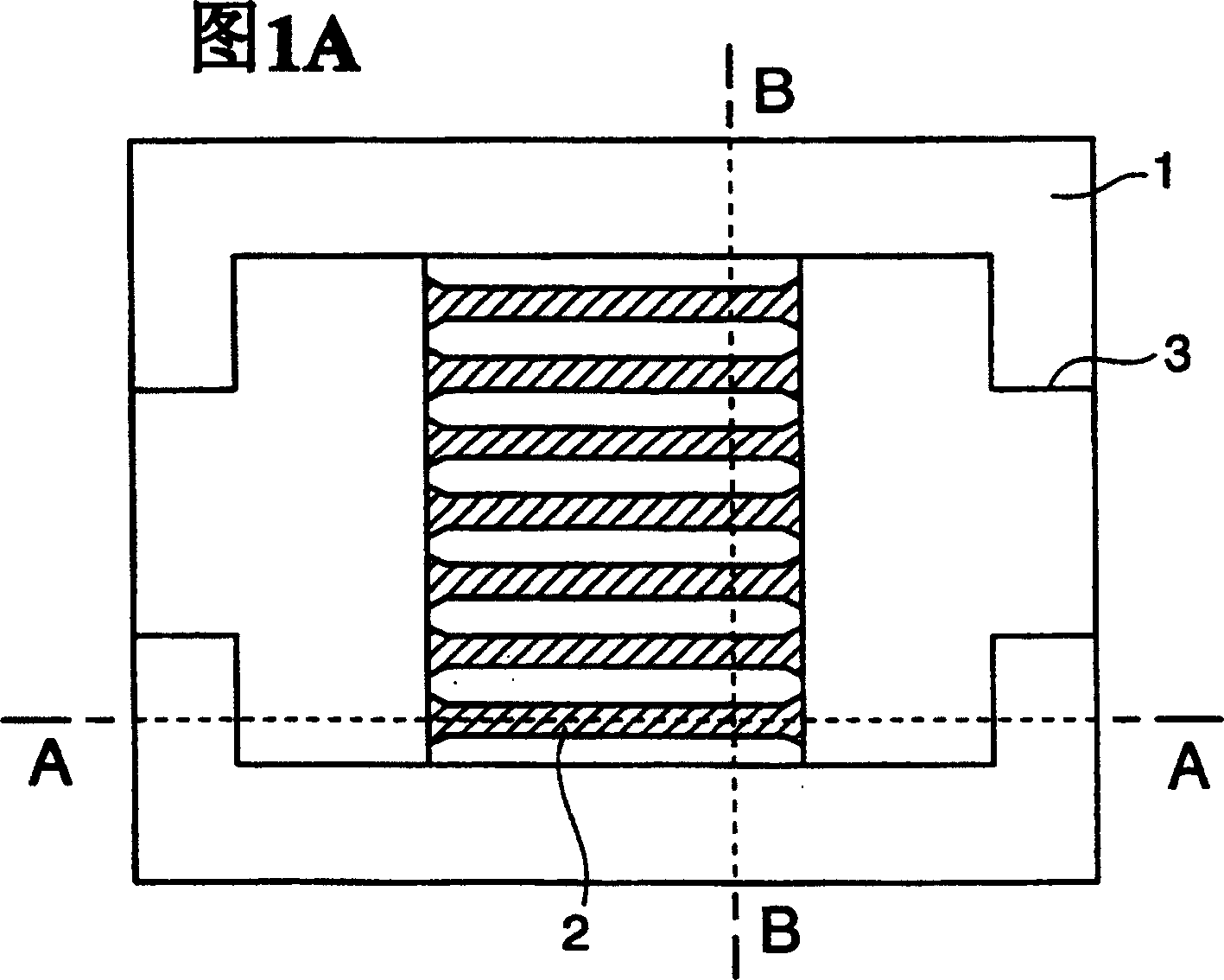
[0053] FIG. 1 is a schematic diagram of a substrate having a heating element according to a first embodiment of the present invention, showing an enlarged portion of the substrate where the heating element is installed. Fig. 61A is a view of the substrate seen from above. also, Figure 1B It is a sectional view taken along the line A-A in FIG. 1A . Figure 1C It is a sectional view along the line B-B in FIG. 1A.
[0054] The substrate 1 is a substrate made of silicon (hereinafter referred to as a silicon substrate). The heating part (membrane) 2 is actually a heating element that can carry heat. In this embodiment, as a material of the heating portion 2 , silicon in which impurities have been diffused is used. As the impurity, for example, boron (B: boron) is preferable. Silicon diffused with impurities such as boron has conductivity.
[0055] Among them, such as Figure 1B As shown, the heating part 2 is a bridge structure suspended (suspended) by the silicon substrate 1...
no. 2 Embodiment approach
[0070] Figure 5A to Figure 5F and Figure 6G to Figure 6M It is a schematic diagram which shows the manufacturing process of the heating element of this embodiment. In the figure, each figure shown on the right shows a sectional view corresponding to the direction of the A-A line shown in FIG. 1A, and each figure shown on the left shows a sectional view corresponding to the direction of the B-B line shown in FIG. 1A. In this embodiment, the oxide film (SiO 2 ) 11 after pattern making, form a boron doped layer 14 on the surface (hereinafter referred to as heating surface 12) constituting the heating portion 2, after forming the protective film 5 for wet etching protection on the heating surface 12, from the heating surface 12 Dry etching and wet etching of silicon are performed on the substrate 1 to obtain a heating element having a cavity shape of the heating portion 2 .
[0071] Hereinafter, a method of manufacturing a heating element will be described with reference to F...
no. 3 Embodiment approach
[0105] Figure 10A with Figure 10B It is a figure which shows the film-forming process of the protective film 5 which concerns on the 3rd Embodiment of this invention. In the above-mentioned first embodiment, in Figure 3I In the shown steps, the film as the protective film 5 is processed in the illustrated shape by performing half etching. In this embodiment, by forming a film as the protective film 5 in two stages, it is processed into Figure 3I the shape shown.
[0106] Therefore, the processing is performed in the following steps instead of the one described in the first embodiment Figure 3I A step of. First, film formation treatment is performed on the insulating film 4 and the wiring 3 by a plasma CVD device, such as Figure 10A As shown, the first-stage film 5a is formed into a film. Then, the film formation process is performed again by the plasma CVD device, such as Figure 10B As shown, by forming the film 5b of the second stage, it is processed into Fig...
PUM
 Abstract
Description
Claims
Application Information
 - R&D
- Intellectual Property
- Life Sciences
- Materials
- Tech Scout
- Unparalleled Data Quality
- Higher Quality Content
- 60% Fewer Hallucinations
Browse by: Latest US Patents, China's latest patents, Technical Efficacy Thesaurus, Application Domain, Technology Topic, Popular Technical Reports.
© 2025 PatSnap. All rights reserved.Legal|Privacy policy|Modern Slavery Act Transparency Statement|Sitemap|About US| Contact US: help@patsnap.com


