Concrete cavity forming mold and use method thereof

A technology for forming molds and concrete, which is applied in the direction of molds, ceramic molding machines, mold fixing devices, etc. It can solve the problems of difficult design, installation and dismantling, large use limitations, and difficult cleaning, and achieves less demoulding workload and long-term use. Stable, easy-to-operate effect

Pending Publication Date: 2020-07-10
HUNAN WUXIN MACHINERY
View PDF0 Cites 0 Cited by
  • Summary
  • Abstract
  • Description
  • Claims
  • Application Information

AI Technical Summary

Problems solved by technology

[0002] At present, there are three main forms of common concrete cavity forming molds: one is the integral cavity mold (abbreviation of the cavity forming mold, the same below), the slope is set along the depth direction of the cavity, and the demoulding is pulled out by the slope. Although the design and production of the cavity mold is relatively simple, there are disadvantages such as changing the structural shape of the cavity, large demoulding force and difficult to guarantee the demoulding quality, and the use is limited; the second is to make multiple loose-assembled cavity molds, This method has a large number of cavity molds, a large amount of assembly and disassembly work, and it is difficult to design, install and dismantle when the cavity cross-sectional area is small and the depth is large, and it is difficult to apply; the third is to make multiple hinged cavity molds. Although the mold closing process is relatively simple, the structure of the cavity mold is complex, and it is easy to form a staggered platform between the panels, the joints of the panels are easy to turn and leak, and it is difficult to clean the gap between the panels, and the cavity has a small cross-sectional area and a large depth. In the case of the same, there are also difficulties in design, installation and removal

Method used


Image

  • Concrete cavity forming mold and use method thereof
  • Concrete cavity forming mold and use method thereof
  • Concrete cavity forming mold and use method thereof

Examples


Embodiment Construction

[0028] The present invention will be described in further detail below in conjunction with the accompanying drawings and specific embodiments.

[0029] Example 1 of Concrete Cavity Forming Mold

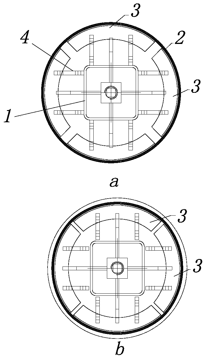
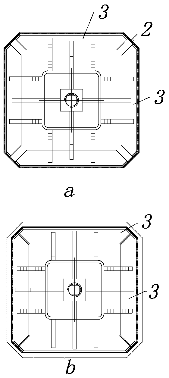
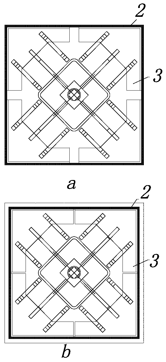
[0030] Figure 1 to Figure 4 An embodiment of the concrete cavity forming mold of the present invention is shown. The concrete cavity forming mold of this embodiment includes a telescopic skeleton 4, an elastic wrapping layer 2 and a plurality of support plates 3, and the plurality of support plates 3 surround the telescopic skeleton The telescopic skeleton 4 is arranged on the outer side of 4 and is connected with the supporting board 3 , and the elastic wrapping layer 2 is arranged on the outer side of a plurality of supporting boards 3 . Wherein, the elastic wrapping layer 2 can be, for example, a rubber layer, a silica gel layer or a steel plate layer, etc.; two of the multiple support plates 3 form a group, and the two support plates 3 in the same group are symmetrically arrange...


PUM


Abstract

The invention discloses a concrete cavity forming mold. The mold comprises a telescopic skeleton, an elastic wrapping layer and multiple supporting plates, the supporting plates are arranged around the outer side of the telescopic skeleton, the telescopic skeleton is connected with the supporting plates, the elastic wrapping layer is mounted on the outer sides of the supporting plates, and a use method of the mold comprises the steps of S1, mold filling, wherein the telescopic framework drives the supporting plates to shrink, the elastic wrapping layer is mounted on the outer sides of the supporting plates, the telescopic skeleton drives the supporting plates to extend until the size of the outer contour of the wrapping layer is consistent with a concrete cavity required to be formed, andfinally, the mold is filled in the position of a cavity; S2, concrete pouring; and S3, mold stripping, wherein during mold stripping, the telescopic framework drives the supporting plates to shrink, the elastic wrapping layer shrinks to be separated from the concrete cavity, and the mold is taken out. The mold has the advantages that the cavity structure does not need to be changed, the mold is suitable for concrete cavities in multiple section shapes, long-term use is stable, and reliability is achieved.

Description

technical field [0001] The invention relates to a concrete mold and a method for using the same, in particular to a mold for forming a concrete cavity and a method for using the same. Background technique [0002] At present, there are three main forms of common concrete cavity forming molds: one is the integral cavity mold (abbreviation of the cavity forming mold, the same below), the slope is set along the depth direction of the cavity, and the demoulding is pulled out by the slope. Although the design and production of the cavity mold is relatively simple, there are disadvantages such as changing the structural shape of the cavity, large demoulding force and difficult to guarantee the demoulding quality, and the use is limited; the second is to make multiple loose-assembled cavity molds, This method has a large number of cavity molds, a large amount of assembly and disassembly work, and it is difficult to design, install and dismantle when the cavity cross-sectional area ...

Claims


Application Information

Patent Timeline
Patent Type & Authority Applications(China)
IPC IPC(8): B28B7/26B28B7/02B28B13/06B28B7/00B28B1/14
CPCB28B1/14B28B7/0002B28B7/0014B28B7/02B28B7/26B28B13/062
Inventor 郑怀臣李佑福吴忠盛毛成宝张维颂曹端雄
Owner HUNAN WUXIN MACHINERY
Why Eureka
Try Eureka