Sterilizing apparatus

a technology of sterilizing apparatus and cleaning utensils, which is applied in the direction of instruments, lavatory sanitizers, disinfection, etc., can solve the problem of not being able to clean such small devices every time using detergents, and achieve the effect of removing bacteria quickly and easily

Active Publication Date: 2019-05-16
SEOUL VIOSYS CO LTD
View PDF2 Cites 20 Cited by
  • Summary
  • Abstract
  • Description
  • Claims
  • Application Information

AI Technical Summary

Benefits of technology

[0007]Exemplary embodiments of the present invention provide a sterilizing apparatus capable of easily and quickly rem

Problems solved by technology

Therefore, although it is necessary to remove bacteria present in such small devices used in contact with the hu

Method used


Image

  • Sterilizing apparatus
  • Sterilizing apparatus
  • Sterilizing apparatus

Examples


Embodiment Construction

[0091]Hereinafter, exemplary embodiments of the present invention will be described in detail with reference to the accompanying drawings. It should be noted that the drawings are not to precise scale and may be exaggerated in thickness of lines or size of components for descriptive convenience and clarity only. In addition, the terms used herein are defined by taking functions of the present invention into account and can be changed according to user or operator custom or intention. Therefore, definition of the terms should be made according to the overall disclosure set forth herein.

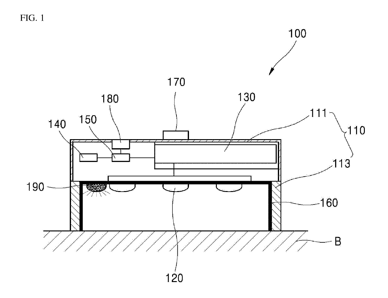
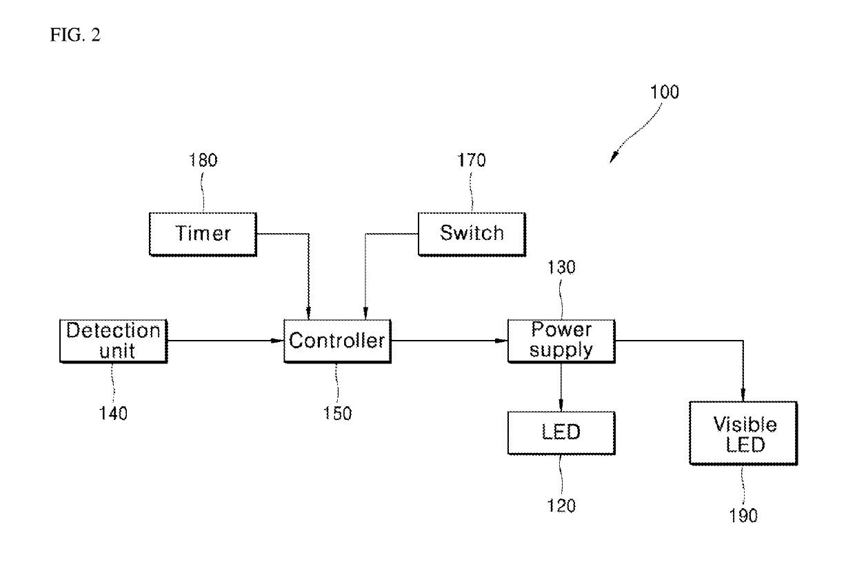
[0092]FIG. 1 is a sectional view of a sterilizing apparatus according to one embodiment of the present invention and FIG. 2 is a block diagram of the sterilizing apparatus according to the embodiment of the present invention.

[0093]Referring to FIGS. 1 and 2, the sterilizing apparatus 100 according to this embodiment may include a cover body 110, a UV light emitting diode 120, a power supply 130, a dete...


PUM


Abstract

A sterilizing apparatus is disclosed. A sterilizing apparatus according to one embodiment comprises: a cover main body unit having an accommodation space formed therein so as to accommodate a device to be sterilized, wherein the accommodation space is open toward a bottom surface on which the device to be sterilized is disposed; an ultraviolet light emitting diode provided on a surface facing the bottom surface of the cover main body unit, and turned on so as to emit ultraviolet rays toward the accommodation space; a power supply unit for supplying power to the ultraviolet light emitting diode so as to turn on the ultraviolet light emitting diode; and a control unit for controlling an operation of the power supply unit.

Description

CROSS-REFERENCE TO RELATED APPLICATION[0001]This application claims priority to and the benefit of Korean Patent Application Nos. 10-2015-0091036, filed on Jun. 26, 2015, 10-2015-0093744, filed on Jun. 30, 2015, 10-2016-0025592, filed on Mar. 3, 2016, and an International Application No. PCT / KR2016 / 006386, filed on Jun. 16, 2016, which are all hereby incorporated by reference for all purposes as if fully set forth herein.BACKGROUNDTechnical Field[0002]The present invention relates to a sterilizing apparatus using a UV light emitting diode to perform sterilization by emitting UV light towards a sterilization target region.Discussion of the Background[0003]Generally, since various kinds of small devices used in contact with the human body, such as earphones, nail clippers, razors, and mobile phones, are stored in various places for user convenience, such as pockets, bags, the interior of vehicles, and the like, such small devices are likely to contact many kinds of bacteria living in ...

Claims


Application Information

Patent Timeline
IPC IPC(8): A61L2/10A61L2/26
CPCA61L2/10A61L2/26A61L2202/11A61L2202/122A61L2202/14A61L2202/121E03C1/126G01B5/24G01B11/02A61L2202/17Y02E60/10
Inventor KIM, JONG RACKJUNG, HEE CHEULJUNG, SANG WOOKBAE, HEE HOKIM, SEONG HEON
Owner SEOUL VIOSYS CO LTD
Why Eureka
Try Eureka