
Anhydrous mechanical seal with self-circulation function

A mechanical seal device and function technology, applied in the direction of engine seal, mechanical equipment, engine components, etc., can solve the problems of short life, poor lubrication of anhydrous mechanical seal, heat generation, etc., to prolong the life, strengthen the flow, and solve the complex structure. Effect

Inactive Publication Date: 2011-04-13
昆明嘉和科技股份有限公司 +2
View PDF6 Cites 2 Cited by
  • Summary
  • Abstract
  • Description
  • Claims
  • Application Information

AI Technical Summary

Problems solved by technology

[0004] The purpose of the present invention is to provide a waterless mechanical seal device with improved fluid flow state, sufficient cooling and lubrication, reliability and long service life for the problems of poor lubrication, serious heat generation and short life of the existing waterless mechanical seals

Method used


Image

  • Anhydrous mechanical seal with self-circulation function

Examples


Embodiment Construction

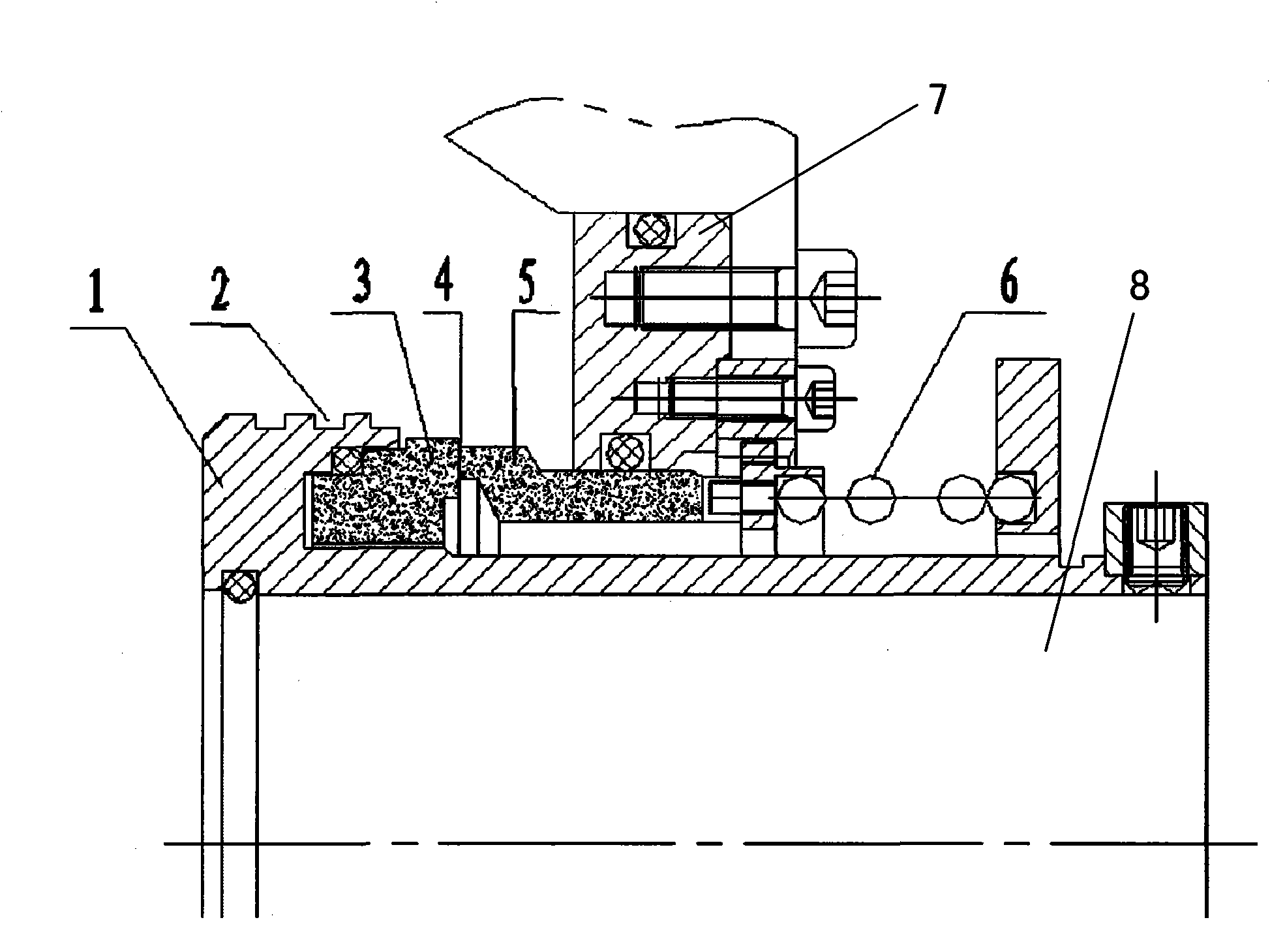
[0012] like figure 1 shown. The sealing device is a single-end structure, does not require external cooling water, and has a self-circulation function, that is, a waterless mechanical seal with a self-circulation function.

[0013] The mechanical seal is composed of a moving ring assembly 1 and a static ring assembly 7 . The moving ring assembly 1 is a rotating ring assembly with a ring-sleeve structure fixed to the rotating shaft 8. The helical groove 2 is arranged on its outer cylindrical surface and is located in the sealing cavity. The inner cavity of the ring sleeve is filled with and fixed silicon carbide material The rotating ring 3; the static ring assembly 6 is fixed with the end cover of the sealing cavity, and the static ring 5 made of silicon carbide is installed and fixed in the inner cavity, and the static ring 5 can move axially along the rotating shaft 8. The end face of the rotating ring 3 is pressed and sealed by the elastic element 6 installed outside the ...


PUM


Abstract

The invention belongs to the field of a mechanical seal, in particular to an anhydrous mechanical seal with a self-circulation function. In the anhydrous mechanical seal device, a moving ring component is arranged in a seal cavity with a fluid, the outer surface of the moving ring component is provided with a spiral groove, and the seal end faces of the moving ring component and a stationary ring component are suppressed and sealed through an elastic element. The anhydrous mechanical seal has the advantages of simple structure, full and reliable cooling and lubrication, and long service life, and can ensure that the flow state of the fluid can be improved.

Description

technical field [0001] The invention belongs to the field of mechanical seals, and in particular relates to an anhydrous mechanical seal with self-circulation effect. Background technique [0002] Mechanical seals are commonly used shaft sealing devices for fluid machinery such as centrifugal pumps. In order to prolong the service life of the mechanical seal, it is often necessary to add flushing water to the mechanical seal of the pump that conveys the solid-liquid two-phase flow medium. One solution is high-pressure flushing, so that the pressure of the flushing water is 0.1-0.2MPa higher than the pressure of the sealing chamber, and then the flushing water is sent into the sealing chamber, and the flushing water enters the sealing chamber after rinsing the sealing end face. The flushing effect of this solution is good, but after a large amount of flushing water enters the sealed cavity, it will cause the dilution of the conveying medium and the loss of flushing water. A...

Claims


Application Information

Patent Timeline
Patent Type & Authority Applications(China)
IPC IPC(8): F16J15/54F16J15/16
Inventor 宋鹏云赵骏丁志浩王静陈兴
Owner 昆明嘉和科技股份有限公司
Learn More