
Method for implementing overload inverse-time protection of alternating-current motor

A technology of inverse time protection and AC motors, applied in the direction of emergency protection circuit devices, electrical components, etc., can solve the problems that cannot satisfy the product monitoring system, cannot meet the change of overload current, and cannot take into account the ability of the motor to withstand overload, etc., to achieve The design is more humanized, conducive to operation, improving reliability and protecting the effect of precision

Inactive Publication Date: 2011-04-13
SHANDONG UNIV OF SCI & TECH
View PDF4 Cites 7 Cited by
  • Summary
  • Abstract
  • Description
  • Claims
  • Application Information

AI Technical Summary

Problems solved by technology

[0002] At present, in many products with electric motors, the motor overload fault protection technology, part of which adopts definite time overload protection. This kind of protection fails to consider the ability of the motor to withstand overload. When the motor is slightly overloaded, the protection will operate after a short delay. , It will inevitably cause unnecessary protection shutdown; some of them adopt staged definite time overload protection, which has a large error and cannot make full use of the overload capacity of the motor, which is unreasonable; the other part adopts inverse time overload protection
Among some overload inverse time protection methods proposed at present, some of them are only applicable to the situation that the overload current is fixed after overloading, and cannot meet the actual problem of overload current change; the other part is based on the method of temperature rise and heat accumulation, comparing the threshold value with The accumulated value is used as the basis for whether to operate. Although it is not affected by the change of overload current, it cannot provide the remaining time of overload action in real time, and cannot meet the needs of some product monitoring systems.

Method used


Image

  • Method for implementing overload inverse-time protection of alternating-current motor
  • Method for implementing overload inverse-time protection of alternating-current motor
  • Method for implementing overload inverse-time protection of alternating-current motor

Examples


Embodiment Construction

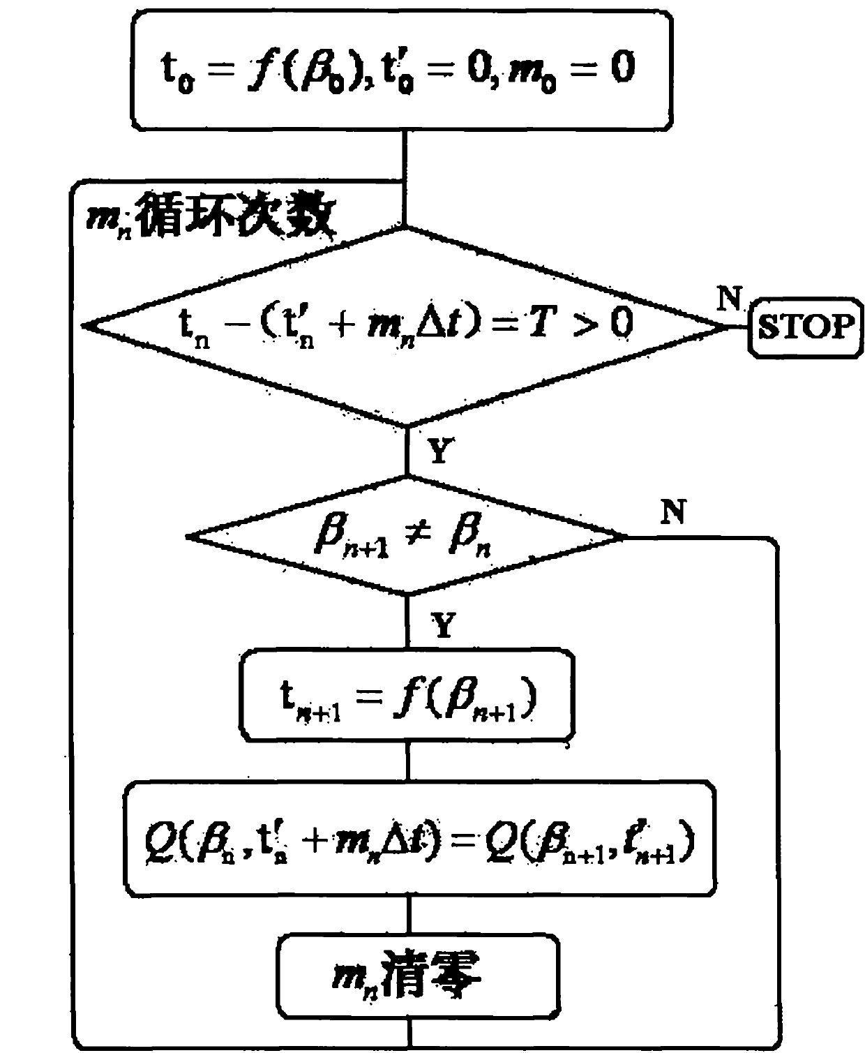
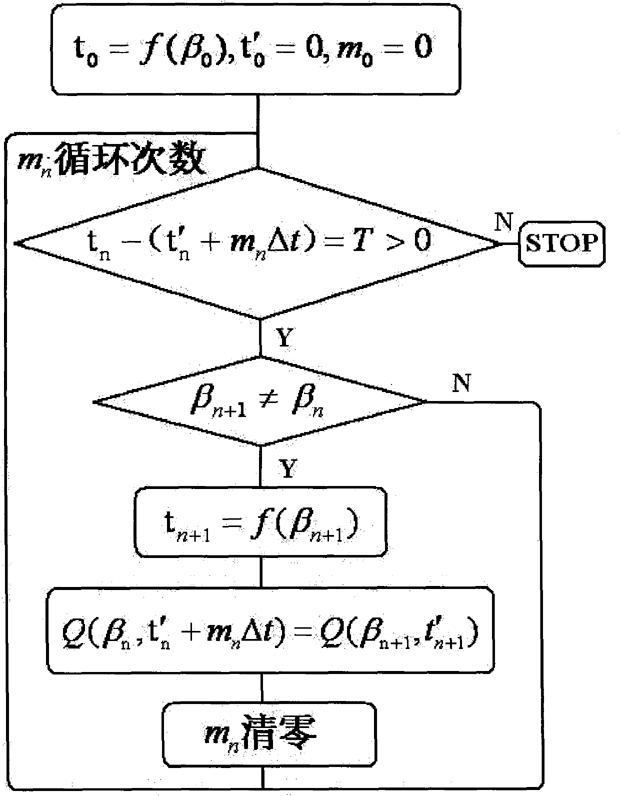
[0027] With reference to the accompanying drawings, a method for realizing overload inverse time protection of an AC motor includes the following steps:

[0028] (1) First, the three-phase current signal value of the AC motor is collected through the current transformer, and the output of the transformer is a DC signal in a certain range, and the arithmetic operation is performed on the microprocessor through A / D conversion. Calculate the load rate β at this time, β=I / I e , I e is the rated operating current of the motor;

[0029] (2) According to the five inverse time-limit action curves recommended in IEC255-4, the mathematical model of the fifth one is

[0030] t = 35.5 τ p ln [ I 2 - I ′ 2 I 2 ...


PUM


Abstract

The invention discloses a method for implementing overload inverse-time protection of an alternating-current motor, which comprises the following steps of: acquiring a three-phase current signal of the motor, calculating the load rate beta at the moment, acquiring inverse-time protection operation time t0 at the moment according to a permissible overload time function t=f(beta) when the beta is greater than a set value, setting a sampling period time as delta t, and acquiring an inverse-time protection operation remaining time T=t0-mdeltat (m is sampling frequency); and if the beta is changed during overload, acquiring a new operation remaining time T=tn-(t'n+mndeltat)n=0,1,2,3,... according to a temperature rise function of the motor, wherein when the T is equal to 0, a peripheral circuit implements protection. The method can make corresponding adjustment according to the change of the overload current during overload to further improve the reliability and protection precision of motor overload protection, can provide protection operation remaining time data for a product monitoring system, and is favorable for operation of a user; and the design is more humanized.

Description

technical field [0001] The invention relates to the technical field of AC motor fault protection, in particular to a method for realizing overload inverse time limit protection of an AC motor. Background technique [0002] At present, in many products with electric motors, the motor overload fault protection technology, part of which adopts definite time overload protection. This kind of protection fails to consider the ability of the motor to withstand overload. When the motor is slightly overloaded, the protection will operate after a short delay. , It will inevitably cause unnecessary protection shutdown; some of them adopt stage-type definite time overload protection, which has a large error and cannot make full use of the overload capacity of the motor, which is unreasonable; the other part adopts inverse time overload protection. Among some overload inverse time protection methods proposed at present, some of them are only applicable to the situation that the overload ...

Claims


Application Information

Patent Timeline
Patent Type & Authority Applications(China)
IPC IPC(8): H02H7/085
Inventor 王瑾陈霞
Owner SHANDONG UNIV OF SCI & TECH
Learn More