

Stator blade for an electric motor
A stator punching and motor technology, which is applied in the field of stator punching, can solve the problems of affecting the efficiency of the motor part, torque, affecting the magnetic field, etc.
- Summary
- Abstract
- Description
- Claims
- Application Information
AI Technical Summary
Problems solved by technology
Method used
Image

Examples
Embodiment Construction
[0037] The present invention will be described in more detail below based on the actual application shown in the blueprint.
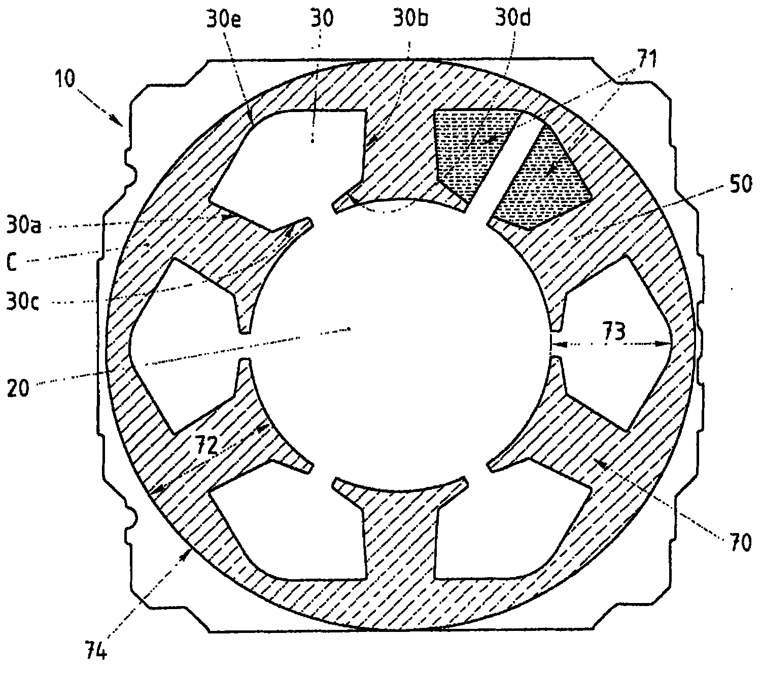
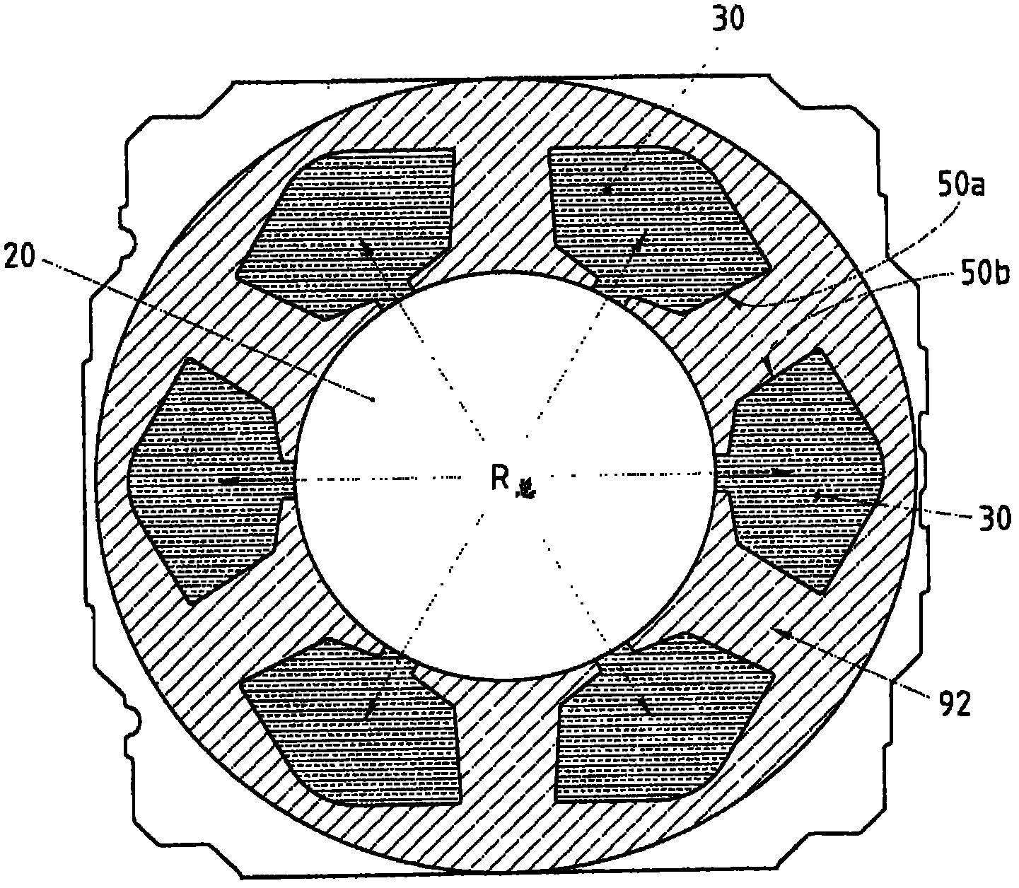
[0038] figure 1 Shown is a typical stator blanking 1 for a compressor motor. The stamping sheet 1 includes a central hole 2 and a plurality of grooves 3 distributed along the central hole 2 . On this punch, the diameter of the center hole is about 55mm.
[0039] The groove 3 is connected to the central bore 2 by a channel or collar 4 . Between two consecutive grooves 3 teeth 5 are formed, the inner edges of these teeth forming the edge of the central hole 2 .
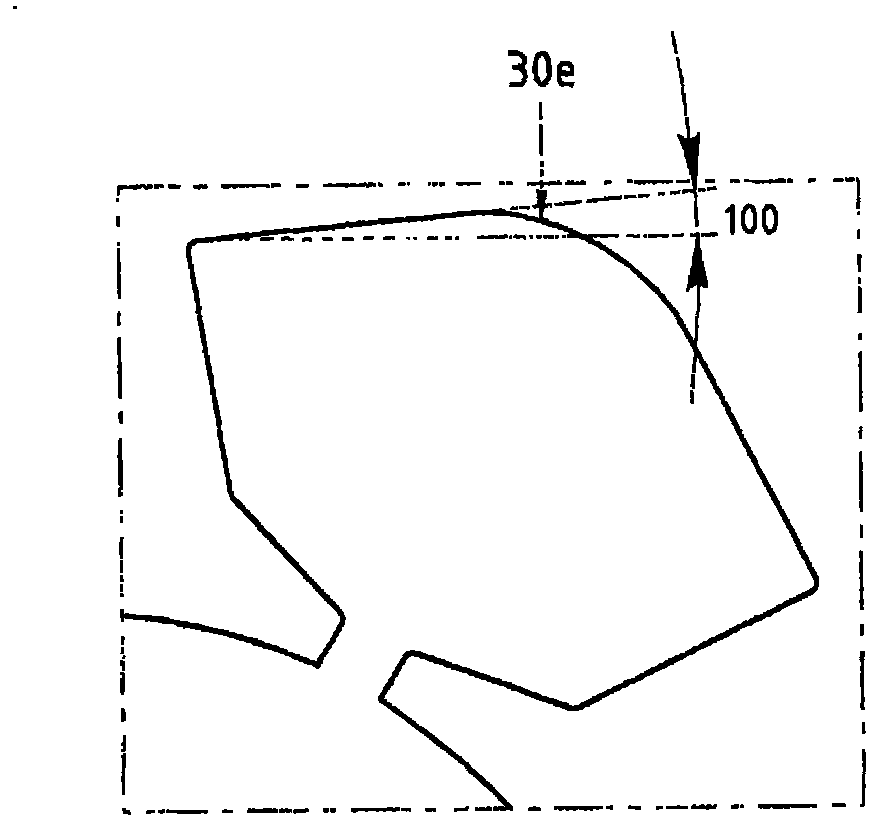
[0040] according to figure 2 As shown, each groove 3 has a shape similar to that of a "sailor's hat", and its internal structure 3 forms an inverted trapezoid 3a, and its upper edge is a rounded oval 3b. Between the trapezoidal and dome-shaped edges (or between the side and upper edges of the groove 3) are curved edges 3c and 3d with a radius of 1.0 mm. The inclination angle formed between...
PUM
 Abstract
Description
Claims
Application Information