
Windshield wiper device

A technology of glass scraping and wiper, which is applied in transportation and packaging, vehicle cleaning, vehicle maintenance, etc., and can solve problems such as irreparable and damaged

Inactive Publication Date: 2011-04-13
ROBERT BOSCH GMBH
View PDF1 Cites 4 Cited by
  • Summary
  • Abstract
  • Description
  • Claims
  • Application Information

AI Technical Summary

Problems solved by technology

[0004] The disadvantage of this construction is, on the one hand, that spare parts such as nuts, washers and the like must be provided by the user in order to fix the windshield wipers during final assembly
A further problem with such knurls is that very high forces can be transmitted via the knurled cone, which can lead to the resulting high forces being introduced into the wiper system when the transmissible torque is exceeded, and may cause irreparable damage in the

Method used


Image

  • Windshield wiper device
  • Windshield wiper device
  • Windshield wiper device

Examples


Embodiment Construction

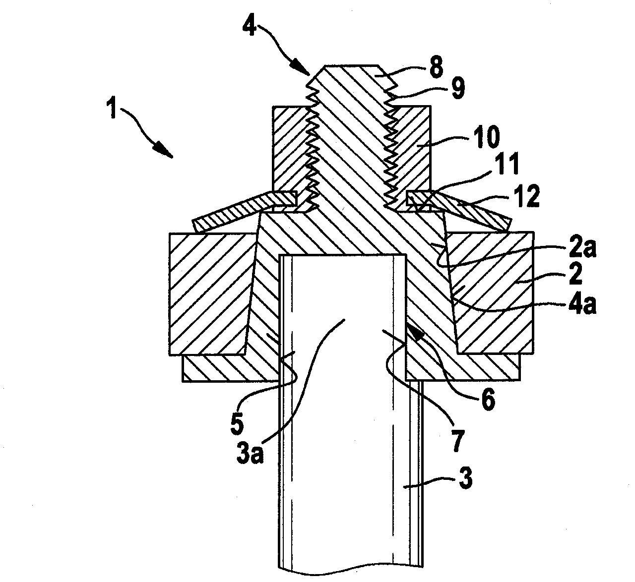
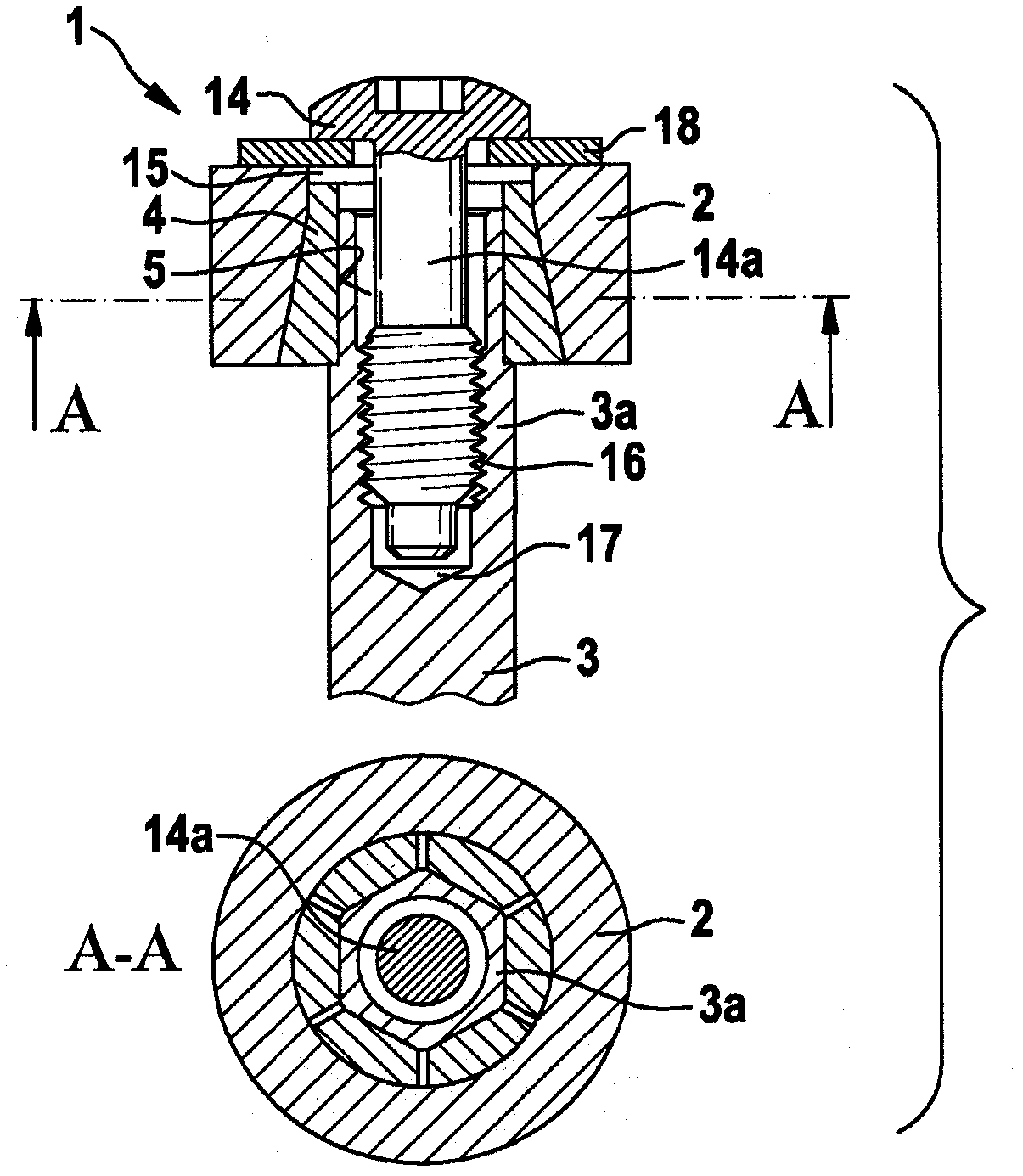
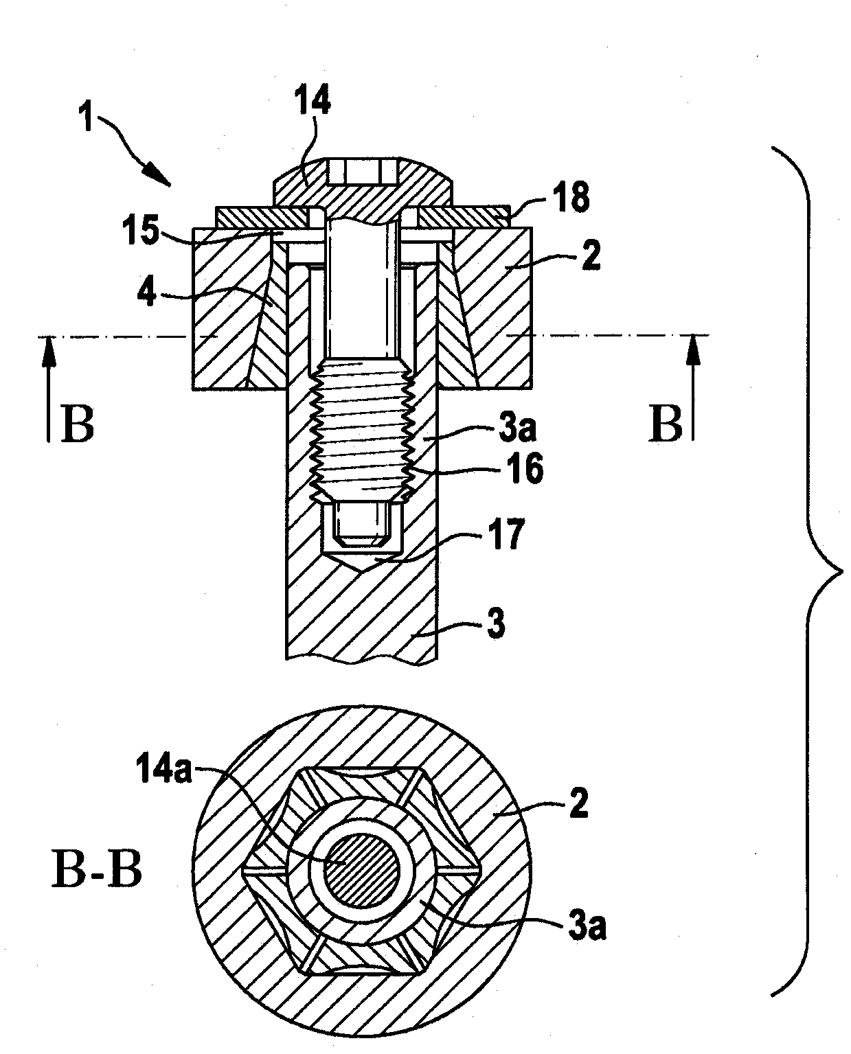
[0027] figure 1A fastening device 1 is shown for fastening a wiper arm 2 to an end section of a driven shaft 3 of a wiper motor of a windshield wiper device, not shown in further detail.

[0028] The fastening mechanism 1 has a connecting part 4 in which an insertion region formed complementary to the end section 3 of the driven shaft 3 is provided in the form of a recess 5 into which the end section is inserted. 3a.

[0029] A non-circular shape is provided as a coupling element in the recess 5 in the form of a support body 6 which is formed complementary to a flat portion 7 formed on the end section 3 a of the driven shaft 3 . This flat part 7 is milled out in the end section 3 a of the driven shaft 3 in a very simple manner. Due to the combination of the support body 6 and the flat part 7 , the coupling piece 4 is prevented from slipping on the driven shaft 3 . Rotation of the output shaft 3 in the connecting part 4 is only possible when a moment is applied which causes ...


PUM


Abstract

The present invention relates to a windshield wiper device, in particular for a rear windshield wiper of a motor vehicle, comprising a wiper motor with one or more driven shafts (3), one or more wiper arms (2), each capable of being attached to an end section (3a) of the driven shaft (3) by way of a fastening mechanism (1), wherein the fastening mechanism (1) comprises a connection piece (4) with a hole (5) provided therein complementary to end section (3a) of the driven shaft (3), said driven shaft (3) able to be inserted into said hole for fastening the connection piece (4) to the wiper motor, wherein a friction-locked connection is made between the connection piece (4) and the driven shaft (3) and / or between the connection piece (4) and the end section (3a) of the driven shaft (3) in the installed state.

Description

technical field [0001] The invention relates to a windshield wiper device, in particular for a rear window wiper of an automobile, having a wiper motor with one or more driven shafts, and having one or more wiper arms, said The wiper arms can each be fastened to an end section of the driven shaft by fastening means. Background technique [0002] A windshield wiper device of the aforementioned type is widely known and is described, for example, in DE 10 2006 007 350 A1. A windshield wiper for motor vehicles is known from this document, which is arranged on a frusto-conical end section of an output shaft. Knurling is formed on the frusto-conical end section transitioning into the screw. The knurling of the frustoconical end section engages in a frustoconical hub at the end of the wiper arm of the windshield wiper. The purpose of the knurling is to prevent the windshield wiper from twisting relative to the output shaft. [0003] In order to fix the windshield wiper on the o...

Claims


Application Information

Patent Timeline
IPC IPC(8): B60S1/34
CPCB60S1/3459
Inventor A·本纳J·齐默P·卡尔克施密特T·博斯J·黑勒A·克劳斯
Owner ROBERT BOSCH GMBH
Learn More