Air conditioner
A technology of air conditioners and outdoor units, applied in the field of air conditioners, can solve the problems of inability to properly perform heat exchange and obtain cooling effects, and achieve the effect of reducing the impact
- Summary
- Abstract
- Description
- Claims
- Application Information
AI Technical Summary
Problems solved by technology
Method used
Image

Examples
no. 1 approach
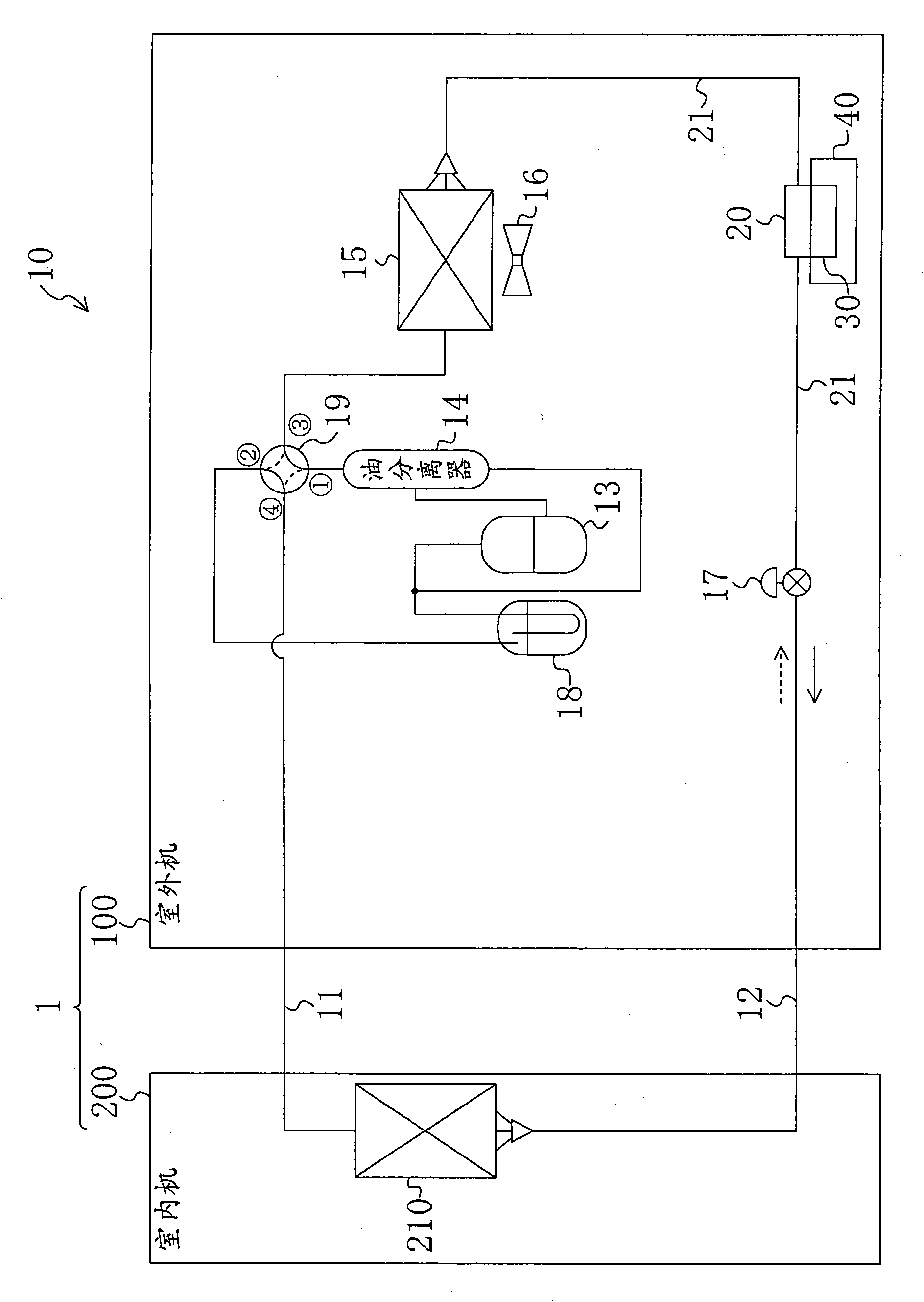
[0029] figure 1 It is a piping diagram of the refrigerant circuit 10 in the air conditioner 1 according to the first embodiment of the present invention. This air conditioner 1 is a heat pump air conditioner capable of cooling operation and heating operation. Such as figure 1 As shown, the air conditioner 1 has an outdoor unit 100 installed outdoors and an indoor unit 200 installed indoors. The outdoor unit 100 and the indoor unit 200 are connected to each other via the first connecting pipe 11 and the second connecting pipe 12 to form a refrigerant circuit 10 that circulates a refrigerant to perform a vapor compression refrigeration cycle.
[0030]
[0031] The indoor unit 200 is provided with an indoor heat exchanger 210 for exchanging heat between the refrigerant and indoor air. As the indoor heat exchanger 210, for example, a cross fin type fin-and-tube heat exchanger or the like can be used. In addition, an indoor fan (not shown) is installed near the indoor heat ex...
no. 2 approach
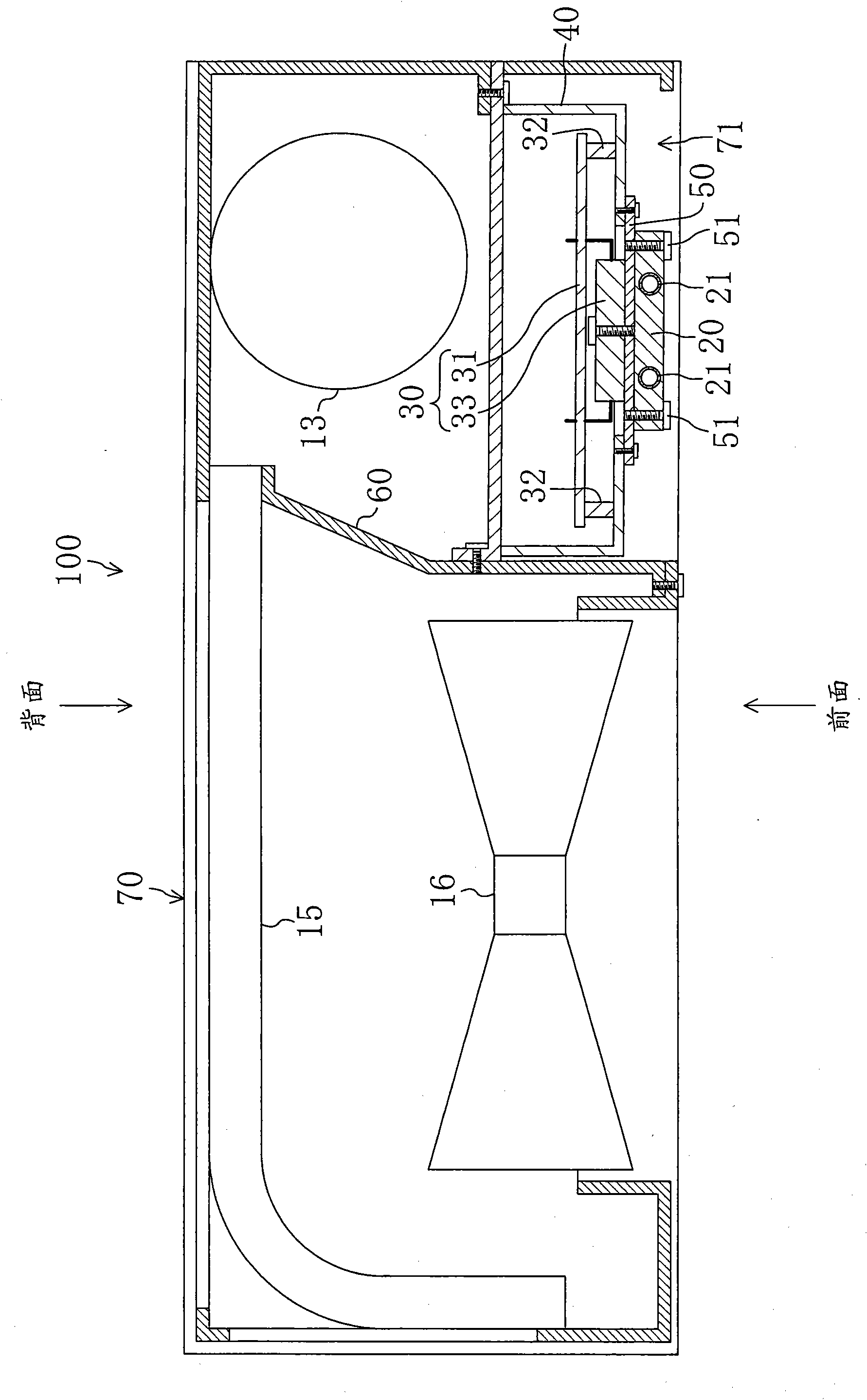
[0051] Figure 5 It is a schematic diagram showing the cross-sectional shape of the outdoor unit 300 according to the second embodiment of the present invention. Such as Figure 5 As shown, in the outdoor unit 300, the installation position of the switch box 40 is different from the installation position of the switch box in the outdoor unit 100 of the first embodiment.
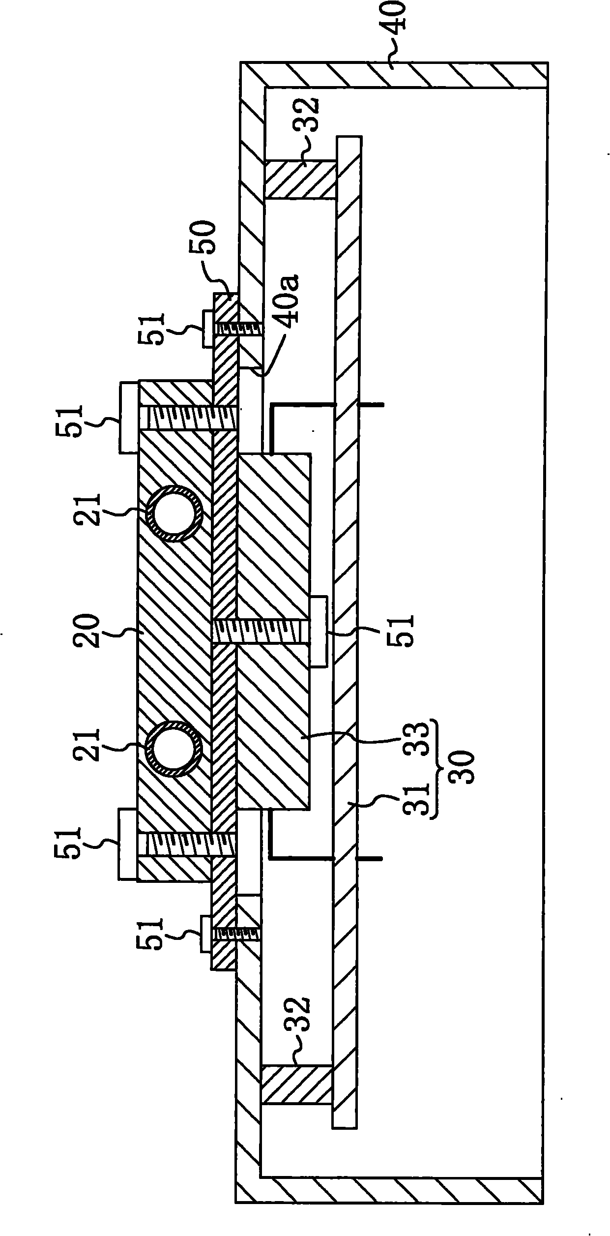
[0052] In this embodiment, if Figure 5 As shown, an operation opening 71 is formed on a side surface of the outdoor unit casing 70 , and the refrigerant jacket 20 is provided at a position close to the operation opening 71 . Furthermore, an attachment opening 72 is formed on a surface (in this example, the front surface of the outdoor unit casing 70 ) adjacent to the surface provided with the working opening 71 . The mounting opening 72 has an opening size large enough to allow the switch box 40 to pass through, and is open to the space on the rear side of the refrigerant jacket 20 (inner side of the outd...
no. 3 approach
[0055] Figure 6 It is a schematic diagram showing the front shape and the side cross-sectional shape of the outdoor unit 400 according to the third embodiment of the present invention. The outdoor unit 400 of this embodiment is characterized by the method of mounting the printed circuit board 31 . That is, in this embodiment, if Figure 6 As shown, the printed circuit board 31 is vertically installed so that the power element 33 is on the upper side.
[0056] Accordingly, the heat dissipated into the air from the power element 33 is transferred upward along with the flow of the air. Therefore, in this outdoor unit 400, the heat dissipated from the power element 33 to the air can hardly be transferred to other circuit elements through the air, thereby reducing the heat dissipated from the power element 33 to other elements on the printed circuit board 31. Impact.
[0057] -Industrial Applicability-
[0058] The air conditioner according to the present invention is useful ...
PUM
 Abstract
Description
Claims
Application Information
PatSnap Eureka turns technology decisions into work you can execute. Powered by our Innovation Knowledge Graph, it runs expert workflows across engineering, life sciences, materials and intellectual property. Get your review-ready output in minutes.


