High-speed shielded flat cable
A flat cable, shielded technology, applied in the field of high-speed shielded flat cables, can solve the problem of poor high frequency characteristics, and achieve the effect of reducing the number of cores
- Summary
- Abstract
- Description
- Claims
- Application Information
AI Technical Summary
Problems solved by technology
Method used
Image

Examples
no. 1 approach
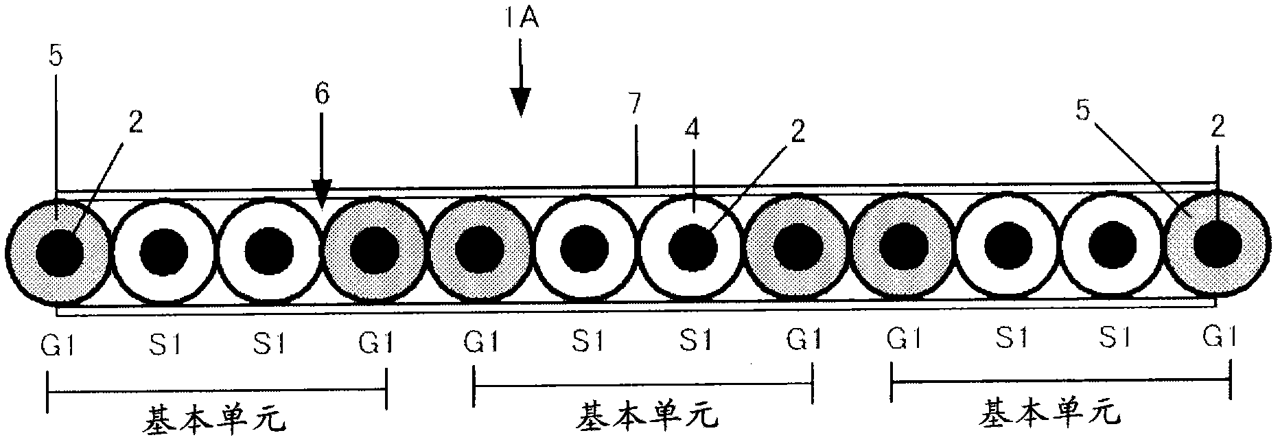
[0037] Such as figure 1 As shown, a high-speed shielded flat cable 1A according to the first embodiment has a signal line S1 whose outer periphery of a conductor 2 is covered with an outer peripheral insulator 4, and a ground wire G1 whose outer periphery of the conductor 2 is covered with a conductive resin 5, and is used for balancing For balanced transmission, two signal lines S1, S1 are arranged side by side in the center, and ground lines G1, G1 are arranged side by side on both sides, thereby forming a basic unit (G1, S1, S1, G1). Then, the basic units are arranged so that one or more of the substrate units are arranged side by side, and the outer peripheral insulators 4 of the adjacent signal lines S1, S1 are bonded or welded together to form the flat cable 6 . In addition, shielding members 7, 7 are closely attached to the upper and lower sides of the flat cable 6, respectively, and the ground wires G1, G1 on both sides are electrically connected to the upper and lower ...
no. 2 approach
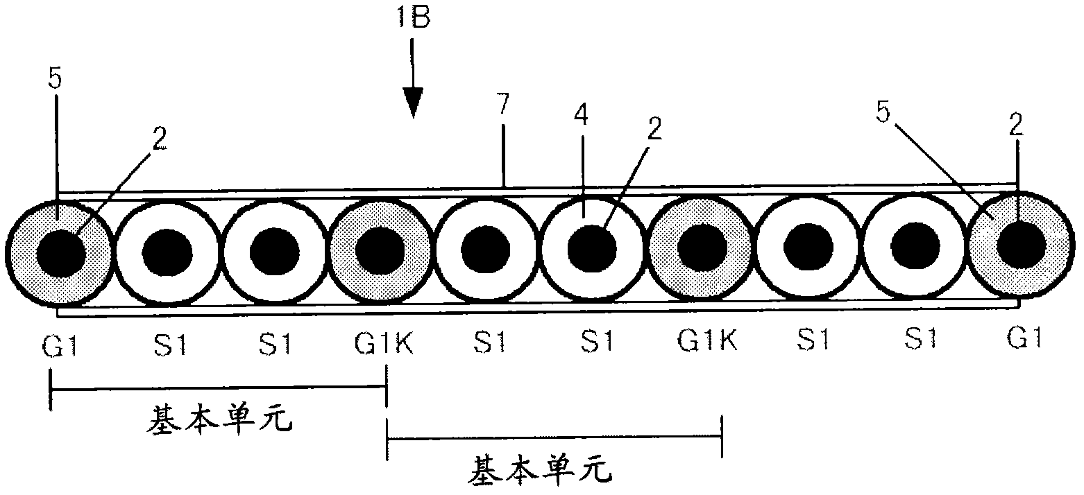
[0040] figure 2 is a configuration sectional view of a high-speed shielded flat cable according to a second embodiment of the present invention. Such as figure 2 As shown, the high-speed shielded flat cable 1B of the second embodiment uses the signal line S1 and the ground line G1 having the same structure as the first embodiment, and when used for balanced transmission, two signal lines S1 and S1 are arranged side by side in the center. , and the ground wires G1 and G1 are arranged side by side on both sides thereof, thereby constituting the basic unit. In the basic unit, the outer peripheral insulators 4 of adjacent signal lines S1 , S1 are bonded or welded to each other to form a flat cable 6 . Furthermore, shielding members 7 , 7 are provided on the upper and lower sides of the flat cable 6 in close contact with each other, and the ground wires G1 , G1 on both sides are electrically connected to the upper and lower shielding members 7 , 7 .
[0041] The high-speed shi...
no. 3 approach
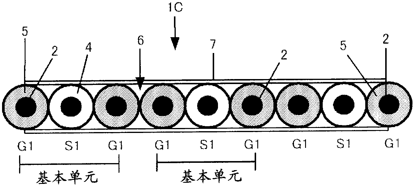
[0047] Fig. 3 is a cross-sectional view showing the structure of a high-speed shielded flat cable according to a third embodiment of the present invention. Such as Figure 3A As shown, the high-speed shielded flat cable 1C of the third embodiment has a signal line S1 whose outer periphery of a conductor 2 is covered with an outer peripheral insulator 4 and a ground wire G1 whose outer periphery of the conductor 2 is covered with a conductive resin 5, and is used for unbalanced transmission. In the case of (unbalanced transmission), the ground lines G1 and G2 are arranged in parallel on both sides of the signal line S1 arranged in the center, thereby constituting a basic unit (G1, S1, G1). Further, the basic units are arranged side by side so that one or more of the substrate units are arranged side by side, and the outer peripheral insulators 4 of the adjacent signal lines S1 , S1 are bonded or welded to each other to form the flat cable 6 . In addition, shielding members 7, ...
PUM
 Abstract
Description
Claims
Application Information
 - R&D
- Intellectual Property
- Life Sciences
- Materials
- Tech Scout
- Unparalleled Data Quality
- Higher Quality Content
- 60% Fewer Hallucinations
Browse by: Latest US Patents, China's latest patents, Technical Efficacy Thesaurus, Application Domain, Technology Topic, Popular Technical Reports.
© 2025 PatSnap. All rights reserved.Legal|Privacy policy|Modern Slavery Act Transparency Statement|Sitemap|About US| Contact US: help@patsnap.com