Supercharge Your Innovation With Domain-Expert AI Agents!

Die ejection discharge device

A mold and concave mold technology, applied in the field of discharging devices, can solve the problems of unsafety and low efficiency of manual discharging of molds, and achieve the effect of improving safety and improving discharging efficiency

Inactive Publication Date: 2011-04-20
李立群
View PDF0 Cites 14 Cited by
  • Summary
  • Abstract
  • Description
  • Claims
  • Application Information

AI Technical Summary

Problems solved by technology

[0003] The purpose of the present invention is to solve the problem of low efficiency and unsafety of manual discharging of existing moulds, and to provide a high-efficiency and safe horizontal tool ejection and discharge device

Method used


Image

  • Die ejection discharge device
  • Die ejection discharge device
  • Die ejection discharge device

Examples


Embodiment Construction

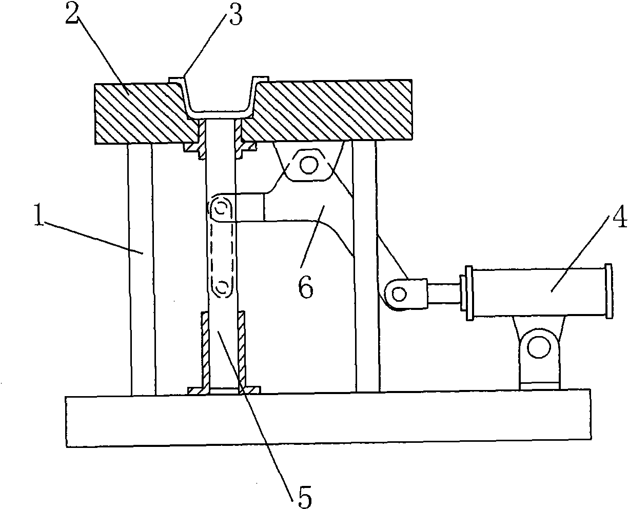
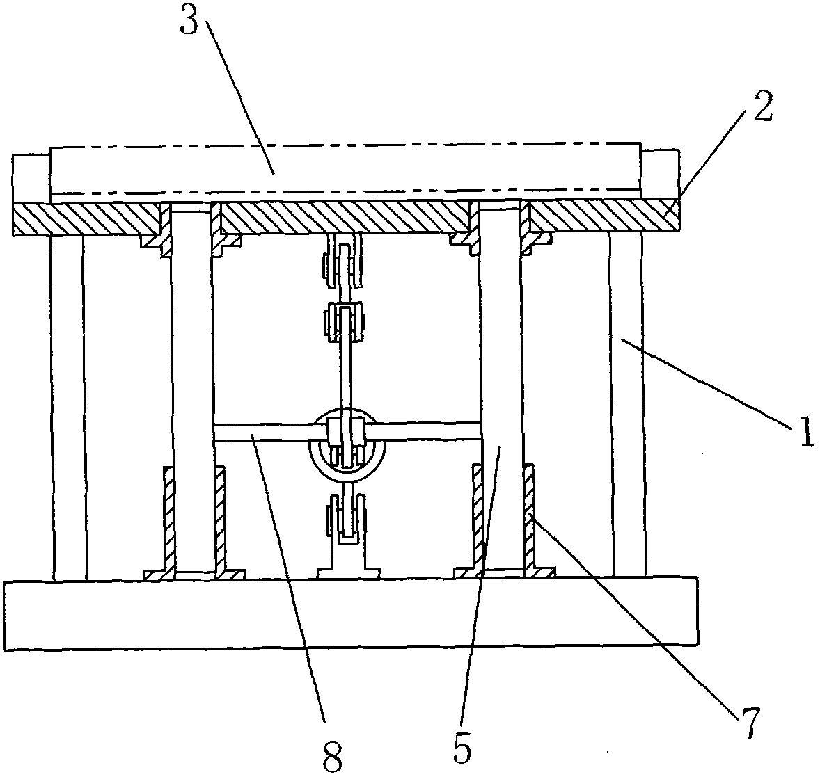
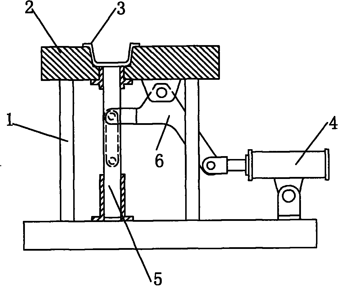
[0010] Mold ejection and discharging device of the present invention, such as figure 1 , figure 2 As shown, it includes a bracket 1 used to fix the die 2, a cylinder 4 hinged on the bracket 1 and a connecting rod 6 connected to the piston rod of the cylinder 4, two through holes are arranged on both sides of the groove of the die 2, through which A push rod 5 is provided in the hole, and the lower end of the push rod 5 is placed in the chute 7 fixed on the bottom of the bracket 1, so that the push rod 5 can slide up and down along the chute 7; a cross bar 8 is fixedly connected between the two push rods 5 The connecting rod 6 is L-shaped, the corner is hinged below the die 2, the front end is movably connected with the cross bar 8, and the rear end is connected with the cylinder 4 piston rod.

[0011] The cylinder 4 of the present invention can also be completed by other mechanical drive methods.


PUM


Abstract

The invention discloses a die ejection discharge device comprising a bracket [1], a cylinder [4] and a connecting rod [6] connected with the piston rod of the cylinder [4]. Two through holes are arranged at the two sides of the groove of a cavity die [2], ejector rods [5] are arranged in the through holes, and the lower ends of the ejector rods [5] are arranged in slide groove [7] fixed at the bottom of the bracket [1] so that the ejector rods [5] can slide up and down in the slide groove [7]. The two ejector rods [5] are fixedly connected by a cross rod [8]. The connecting rod [6] is L-shaped, the corner part is hinged below the cavity die [2], the front end is movably connected with the cross rod [8], and the rear end is connected with the piston rod of the cylinder [4]. The discharge efficiency is largely improved, and the operation safety is largely improved.

Description

technical field [0001] The invention relates to a discharging device, in particular to a die stamping discharging device. Background technique [0002] Molds are widely used in enterprises. After the mold is stamped to form a product, it needs to be discharged from the die. For the discharge of larger products, the operator manually takes out the formed product from the die. The disadvantage of the above-mentioned discharge method is that the product is often tightly squeezed with the die, and manual discharge is very difficult, so the discharge efficiency is low. Secondly, manual discharge in the mold is not safe for the operator. Contents of the invention [0003] The purpose of the present invention is to solve the problems of low efficiency and unsafety of manual discharging of existing molds, and provide a device for ejecting and discharging horizontal tools with high efficiency and good safety. [0004] The technical solution adopted in the present invention: mold...

Claims


Application Information

Patent Timeline
IPC IPC(8): B21D45/02B21D37/12
Inventor 李立群
Owner 李立群
Features
  • R&D
  • Intellectual Property
  • Life Sciences
  • Materials
  • Tech Scout
  • Unparalleled Data Quality
  • Higher Quality Content
  • 60% Fewer Hallucinations
Learn More