
Film stress measuring equipment and film stress measuring method

A technology of thin film stress and measuring equipment, which can be used in measuring devices, measuring and instruments by measuring the changing force of optical properties of materials when they are stressed, and can solve the problems of low degree of automation and low precision.

Inactive Publication Date: 2011-04-20
徐建康
View PDF6 Cites 32 Cited by
  • Summary
  • Abstract
  • Description
  • Claims
  • Application Information

AI Technical Summary

Problems solved by technology

[0003] In order to overcome the defects of low automation and low precision of the existing thin film stress measurement equipment, the present invention aims to provide a non-contact thin film stress measurement equipment with high precision and simple operation and its measurement method

Method used

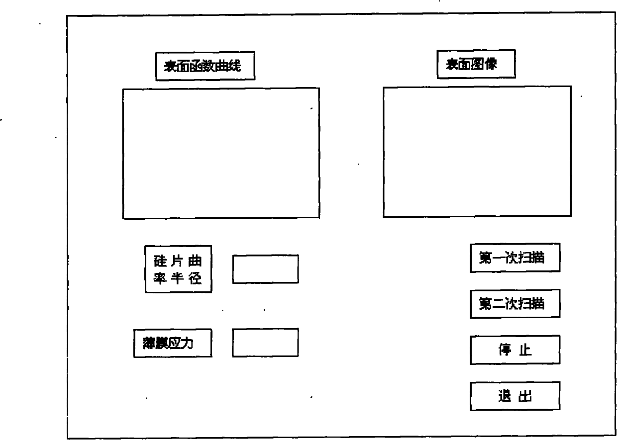
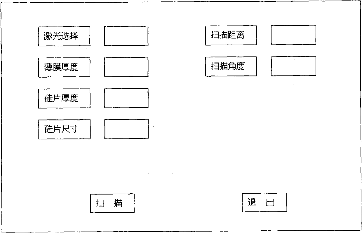

Image

  • Film stress measuring equipment and film stress measuring method
  • Film stress measuring equipment and film stress measuring method
  • Film stress measuring equipment and film stress measuring method

Examples


Embodiment Construction

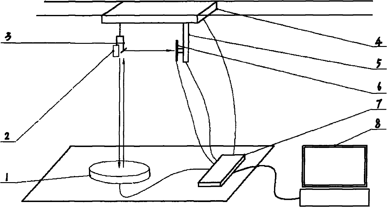
[0034] like figure 1 As shown, in the cuboid equipment case, the laser LED 2, the optical mirror 3, the linear slide rail 4, the detector 6, and the linear slide rail 5 are all connected to the top surface of the equipment case, and the linear slide rail 5 is placed on the linear slide rail 4 below and connected vertically, the tray 1 and the A / D data acquisition card 7 are placed on the inner bottom surface of the equipment case, the tray 1, the A / D data acquisition card 7, the linear slide rail 4, the detector 6, and the linear slide rail 5 All are connected with the computer 8 outside the box of cuboid equipment through circuit. Wherein, the linear slide rail 4 is parallel to the surface of the tray 1 and is located directly above the tray 1 . The linear slide rail 4 is connected with a micro stepping motor outside the equipment through a circuit, and is controlled by the stepping motor. The tray 1 is connected with a micro stepping motor outside the device through a circ...


PUM


Abstract

The invention relates to film stress measuring equipment and a film stress measuring method. In a cuboid equipment case, a laser LED, an optical reflector, a linear sliding rail, a detector and another linear sliding rail all are connected with the top face of the equipment case; the linear sliding rail is arranged below and vertically connected with another sliding rail; a tray and an analog / digital (A / D) data acquisition card are arranged on the internal bottom face of the equipment case; and the tray, the A / D data acquisition card, the linear sliding rail, the detector and the other linear sliding rail are all connected with a computer outside the equipment case through a circuit. In the equipment, a light sensitive electrical detector is used for automatically tracking light path deflection and acquiring a light path deflection displacement signal, a micro step motor is used to control and rotate the tray to quickly generate a silicon chip accurate region curvature and stress change color drawing that helps to get the condition of a thin film on the surface of an entire silicon chip, two-dimensional and three-dimensional images of the surface of the thin film can be obtained, a friendly interface can be written in VC++ language, and it is possible to further expand program functions.

Description

technical field [0001] The invention relates to a non-contact film stress parameter measuring device and a measuring method thereof, in particular to a film stress measuring device and a measuring method thereof. Background technique [0002] At present, many people have conducted a lot of research on the reasons for the stress of the film, and put forward various theoretical foundations which can be attributed to the following two aspects: one aspect is caused by the different thermal expansion of the film and the substrate. During the coating process, the temperature of the film and the substrate rises at the same time, and after the coating, when the temperature drops to the initial temperature, due to the difference in thermal expansion coefficient of the film and the substrate, internal stress is generated, which is generally called thermal stress; On the one hand, it is caused by the non-equilibrium in the film growth process or the unique microstructure of the film, w...

Claims


Application Information

Patent Timeline
Patent Type & Authority Applications(China)
IPC IPC(8): G01L1/24G01B11/255
Inventor 徐建康
Owner 徐建康
Learn More