
Temperature controllable automobile seat

A technology for car seats and control valves, applied to seat heating/ventilation devices, vehicle components, circuits or fluid pipelines, etc. Good stability, stable and reliable effect

Inactive Publication Date: 2017-09-15
TAICANG TAOXIN INFORMATION TECH CO LTD
View PDF0 Cites 6 Cited by
  • Summary
  • Abstract
  • Description
  • Claims
  • Application Information

AI Technical Summary

Problems solved by technology

[0002] With the mass use of cars in society, people's requirements for car seats are getting higher and higher. A variety of multi-functional seats emerge in an endless stream to meet people's different needs, such as ventilated seats, which are air-conditioned seats. The car seat with exchange function completes the exchange of hot air through the ventilation holes installed in the seat. Especially in summer, although the car is equipped with an air conditioner, it can complete the cooling in the car, but the body of the passenger and the seat The contact surface of the seat cannot be cooled because of the mutual bonding. In winter, the temperature of the car seat will also affect the passenger experience due to the low temperature.
[0003] The current car ventilated seats use fans to blow air, and then send the wind into the openings on the surface of the seat to complete the air exchange. This effect is not very good, and the ventilation holes are often squeezed due to the weight of the person. It will affect the air flow and reduce the cooling effect. In addition, the cooling process cannot be regulated, and it cannot be controlled more intelligently and conveniently. When heating, it is heated by a heating wire, and neither heating nor cooling is very good. All in one

Method used


Image

  • Temperature controllable automobile seat
  • Temperature controllable automobile seat
  • Temperature controllable automobile seat

Examples


Embodiment Construction

[0030] In order to better understand the technical solutions of the present invention, the present invention will be further described in detail below with reference to the drawings and specific embodiments.

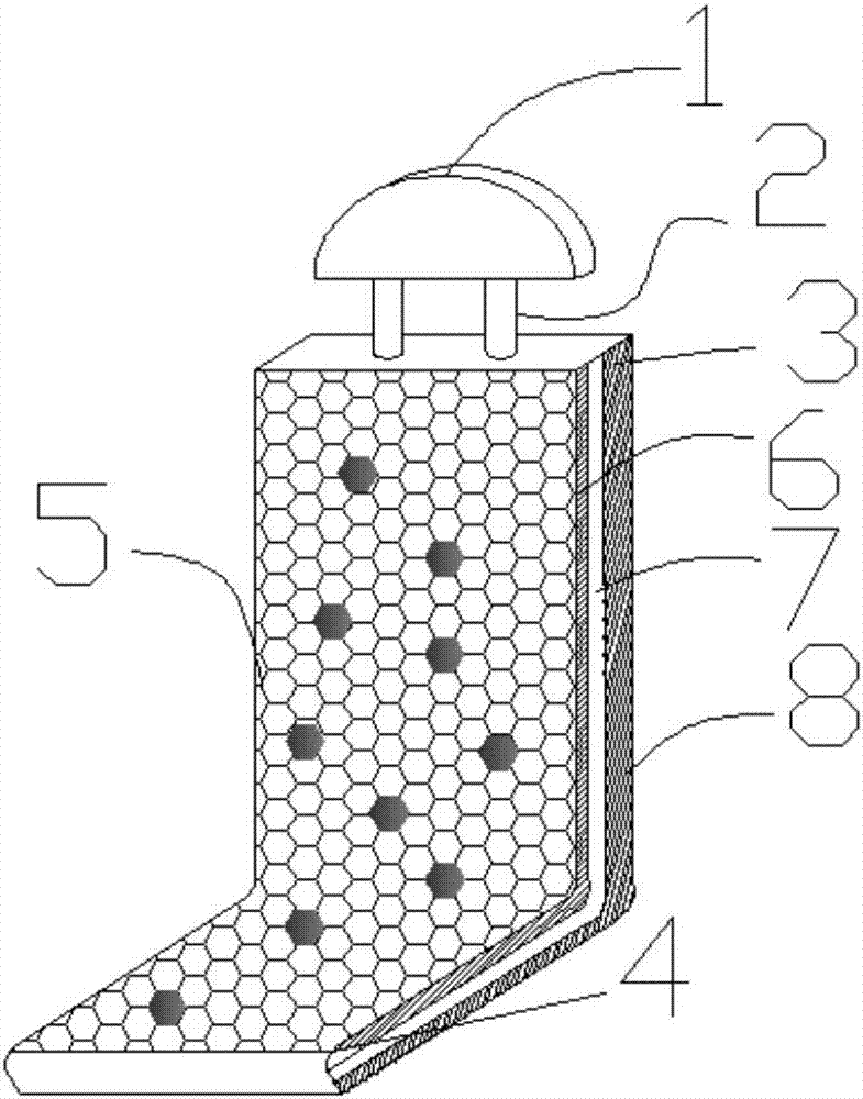
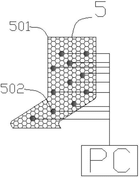
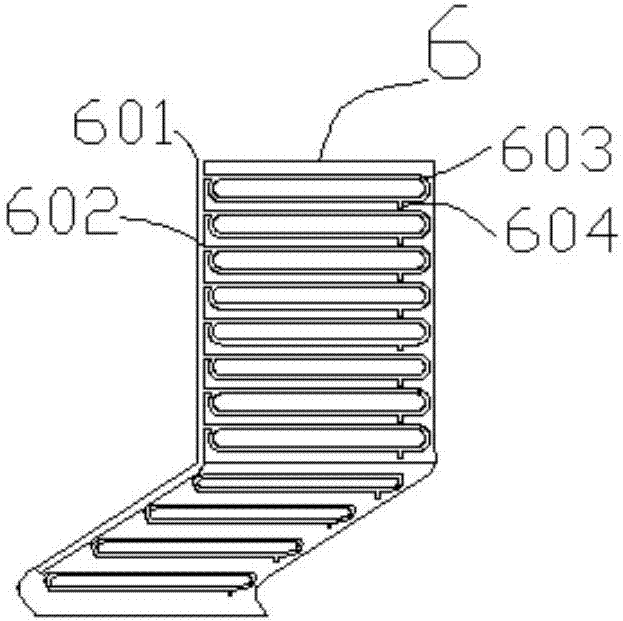
[0031] Reference attached Figure 1-5 As shown, a temperature-controllable car seat mainly includes a headrest 1, a telescopic rod 2, a backrest 3, and a seat cushion 4. It is characterized in that the bottom of the backrest 3 is connected to the seat cushion 4, and the telescopic rod 2 The lower end is installed at the upper end of the backrest 3, and the upper end of the telescopic rod 2 is inserted into the bottom of the headrest 1. The backrest 3 and the seat cushion 4 have the same structure, and both include a surface layer 5, a heat exchange layer 6, and a heat exchange layer that are arranged sequentially from the outer layer to the inner layer. Connecting layer 7 and support layer 8, the heat exchange layer 6 is also connected to a control valve 704 which is electr...


PUM


Abstract

The invention discloses a temperature-controllable car seat. A temperature-controllable car seat mainly includes a headrest, a telescopic rod, a backrest and a seat cushion. The bottom of the backrest is connected to the rear end of the seat cushion. The lower end of the telescopic rod is installed on the upper end of the backrest, and the upper end of the telescopic rod is inserted into the bottom of the headrest. The structure of the backrest and the seat cushion is the same, including a surface layer, a heat exchange layer, a connecting layer and a bracket arranged in sequence from the outer layer to the inner layer. The heat exchange layer is also connected with a control valve, and the control valve is electrically connected with the on-board computer. The invention can monitor the temperature and humidity of the seat and the human monitoring surface in real time through the temperature and humidity sensor installed on the surface layer, and reflect the data to the vehicle-mounted computer, so that people can intuitively understand the situation of the contact surface; the heat exchange layer installed The cold air or warm air sent by the air conditioner is conveyed inside the pipe, and discharged through the exhaust pipe without passing through the air holes, so it is stable and reliable.

Description

Technical field [0001] The invention relates to the field of automobile equipment, in particular to a temperature-controllable automobile seat. Background technique [0002] With the large-scale use of social cars, people’s requirements for car seats are getting higher and higher. Various multifunctional seats are emerging in an endless stream to meet people’s different needs. For example, ventilated seats are a kind of The exchange function of the car seat, through the ventilation holes installed in the seat to complete the exchange of hot air, especially in summer, although the car is installed with air conditioning, can complete the cooling of the car, but the body and seat of the passenger The contact surfaces of the seats cannot be cooled down due to the close contact with each other. In winter, the car seats will also affect the passenger experience due to the low temperature. [0003] The current car ventilated seats are all blown by a fan, and then the wind is sent into th...

Claims


Application Information

Patent Timeline
Patent Type & Authority Applications(China)
IPC IPC(8): B60N2/56B60N2/62B60N2/64B60R16/02
CPCB60N2/56B60N2/62B60N2/64B60R16/02
Inventor 胡敏刚张宇
Owner TAICANG TAOXIN INFORMATION TECH CO LTD
Learn More