Test fixing device

A technology for fixing devices and test pieces, applied in the testing of optical performance, optics, instruments, etc., can solve problems such as affecting test accuracy, and achieve the effect of preventing interference, ensuring stability, and avoiding scratches

Inactive Publication Date: 2011-04-20
SHENYANG CHENXUN SIMCOM TECH
View PDF0 Cites 2 Cited by
  • Summary
  • Abstract
  • Description
  • Claims
  • Application Information

AI Technical Summary

Problems solved by technology

[0003] The technical problem to be solved by the present invention is to overcome the defects of the existing light testing instruments that affect the test accuracy due to manual positioning, and provide a test fixture that can ensure the accuracy of the test and the stability of the test results

Method used


Image

  • Test fixing device
  • Test fixing device
  • Test fixing device

Examples


Embodiment Construction

[0021] The preferred embodiments of the present invention are given below in conjunction with the accompanying drawings to describe the technical solution of the present invention in detail.

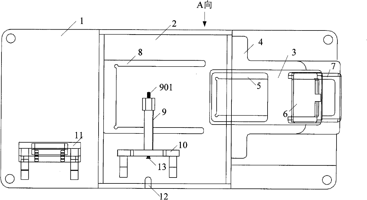
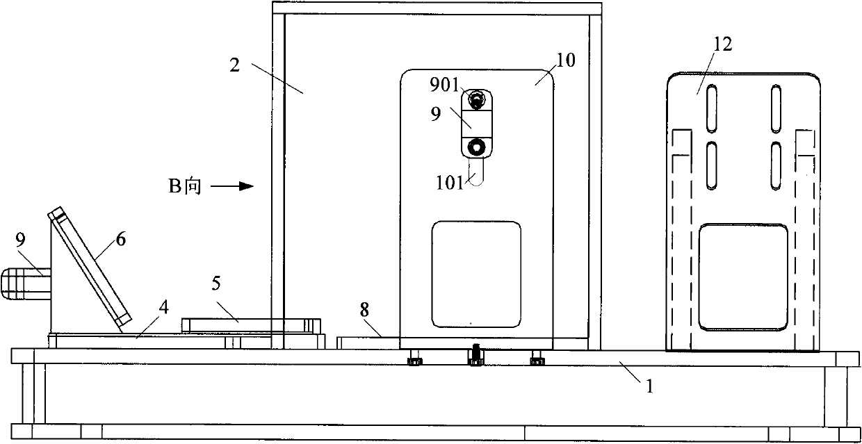
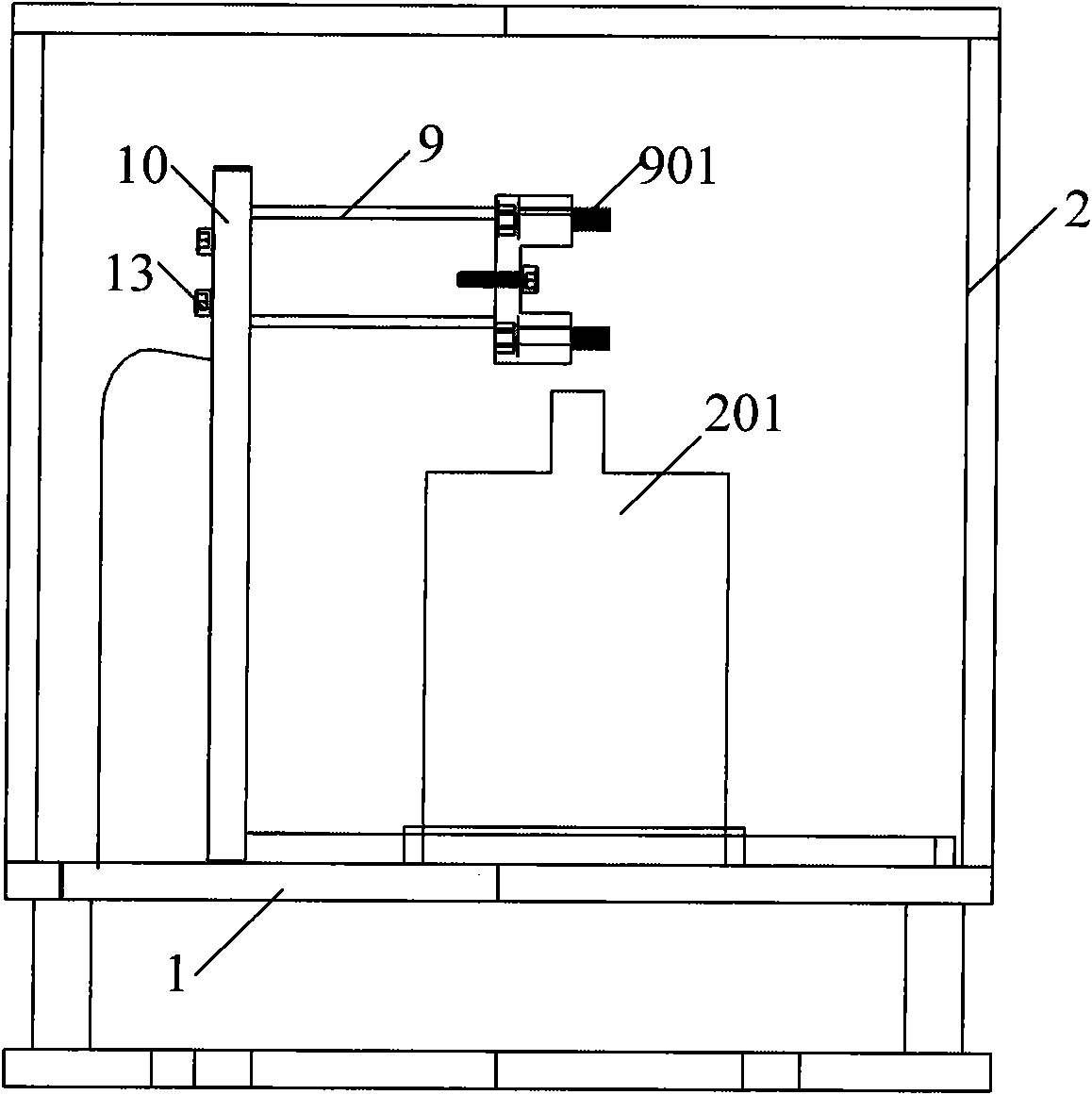
[0022] Such as Figure 1 to Figure 3 As shown, the present invention provides a test fixture, which includes: a base 1, a shielding device arranged on the base 1, a pushing device and a clamping device, wherein the shielding device is a hollow and transparent The square shielding box 2 is used to shield external light interference. The pushing device is used to send the test piece into the shielding box 2 and limit it to a preset testing position. The clamping device is used to clamp the test probe.

[0023] Taking the mobile phone screen test as an example, describe each part of the device in detail. The side wall of the shielding box 2 is provided with a side door 201 for testing mobile phones. The width of the side door 201 corresponds to the shape of the test mobile phone. The p...


PUM


Abstract

The present invention discloses a test fixing device, comprising a base and a shielding device and a push device disposed on the base, wherein the push device and the shielding device are disposed oppositely; the shielding device is used for shielding light interferences; the push device is used for delivering a mobile phone into the shielding device and restricting the mobile phone at a predetermined test position. The device of the present invention can ensure the precision of the test and the stability of test results.

Description

technical field [0001] The invention relates to the production field of liquid crystal display screens, in particular to a test fixture used for light testing of liquid crystal screens. Background technique [0002] Existing screen light test instruments are sensitive to light, and the test equipment usually does not have relevant supporting tooling. There are the following problems: the test position is manually positioned during the test process, which affects the consistency of the test results. In addition, the test results are also easily affected by external light. , causing deviations in test results. Contents of the invention [0003] The technical problem to be solved by the present invention is to overcome the defects of the existing optical testing instruments that affect the testing accuracy due to manual positioning, and provide a test fixture that can ensure the accuracy of the test and the stability of the test results. [0004] The present invention solves...

Claims


Application Information

Patent Timeline
Patent Type & Authority Applications(China)
IPC IPC(8): G01M11/02G02F1/13
Inventor 王洪来任竹岩
Owner SHENYANG CHENXUN SIMCOM TECH
Why Eureka
Try Eureka