Insulated conductor grounding potentiometer

An insulated wire, ground potential technology, applied in conductive connections, wire wound connectors, circuits, etc., can solve the problems of long operation time, easy damage to wires, poor grounding quality of wires, etc., to achieve short operation time, long service life, The effect of high ground quality

Inactive Publication Date: 2011-04-20
WEIHAI POWER SUPPLY COMPANY OF STATE GRID SHANDONG ELECTRIC POWER COMPANY
View PDF0 Cites 15 Cited by
  • Summary
  • Abstract
  • Description
  • Claims
  • Application Information

AI Technical Summary

Problems solved by technology

[0004] Since the specifications and models of domestic insulated wires are not completely uniform, the thickness of the insulation layer is uneven, and there are double insulation layers in the insulated wires used, it is very difficult or even impossible to operate the stripper during use, and it is easy to damage the wires. The existing ground wire clamp is provided with a clamp body, the clamp body is provided with a groove, and a through hole is provided on the lower groove edge of the groove, a pull rod is arranged in the through hole, a movable splint is arranged in the groove, and the movable splint and the pull rod The connecting end of the pull rod and the movable splint is covered with a spring, the other end is provided with a plug cap and a connecting handle, the through hole and the pull rod are correspondingly provided with a chute and a pin, and the movable splint passes through the pull rod, the pin, the through hole chute and The spring can be opened or closed relative to the other side of the groove, and the clip body is provided with connecting holes or bolts and other grounding wire connection devices. state, then hang the edge of the upper groove of the clip body on the grounded wire, then rotate the operating lever to make the pin enter the chute, and under the action of the spring, the movable splint closes to clamp the wire. The disadvantage is that two people are required during the operation. Coordination, inconvenient operation, long operation time, poor grounding quality of wires

Method used


Image

  • Insulated conductor grounding potentiometer
  • Insulated conductor grounding potentiometer
  • Insulated conductor grounding potentiometer

Examples


Embodiment Construction

[0014] The present invention will be further described below in conjunction with accompanying drawing:

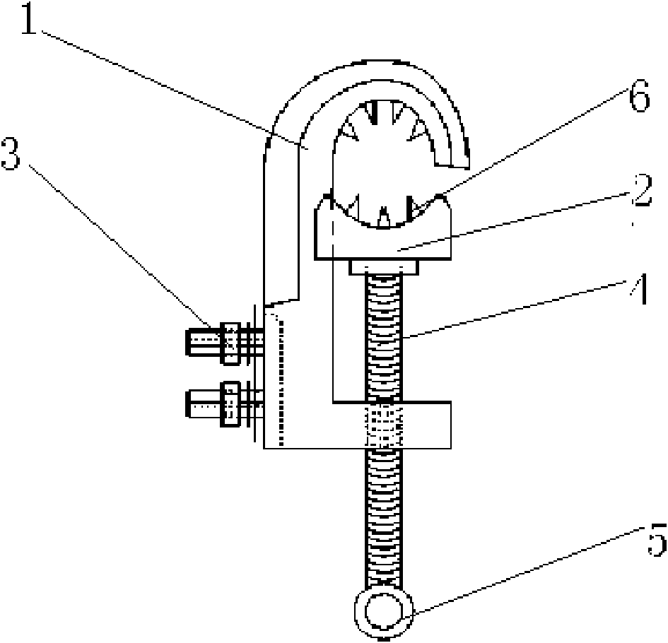
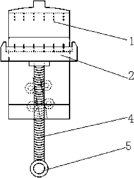
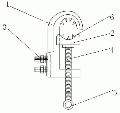
[0015] As shown in the accompanying drawings, a ground potentiometer for insulated wires includes a hook body 1 and a movable splint 2. The hook body 1 is provided with a groove and a grounding wire connection device 3. The upper groove of the hook body 1 is in the shape of a semicircular hook. The lower groove edge of the hook body 1 is provided with a connecting screw hole, the screw rod 4 matches the connecting screw hole, one end of the screw rod 4 is connected with the movable splint 2, and the other end of the screw rod 4 is provided with a connecting handle 5. The working surface of splint 2 can be semicircular, and the upper groove edge of movable splint 2 and hook body 1 can form a circle or a similar circle, and can be respectively set on the upper groove edge of movable splint 2 working surface and hook body 1. There are conductive thorns 6, and the clamping arc ...


PUM


Abstract

The invention relates to a grounding wire device of a transformer substation, in particular to an insulated conductor grounding potentiometer, which comprises a hook body and a movable clamping plate. A groove is formed on the hook body, and a grounding wire connecting device is also arranged on the hook body. The insulated conductor grounding potentiometer is characterized in that: the upper groove edge of the hook body has a hemispherical hook shape; a connecting screw hole is formed on the lower groove edge of the hook body, and is in fit with a threaded rod; one end of the threaded rod is connected with the movable clamping plate; and a connecting handle is arranged at the other end of the threaded rod. When the insulated conductor grounding potentiometer is used, the threaded rod is first rotated to open the movable clamping plate relative to the other groove edge, an operating rod is connected with the connecting handle, the upper groove edge of the hook body of a clamping hook is hung on a grounded electric wire, then the operating rod is rotated to drive the movable clamping plate by the threaded rod to move along the groove, the movable clamping plate and the upper groove edge of the hook body form an arched working surface to tightly clamp the electric wire, and conductive thorns on the arched working surface puncture an insulating layer to tightly contact with the electric wire, so that the electric wire is connected with a grounding wire with high quality. The insulated conductor grounding potentiometer has the advantages of short operation time, labor saving, high grounding quality, safety in use and the like, and is convenient to operate.

Description

Technical field: [0001] The invention relates to a grounding wire device of a substation, in particular to a potentiometer for an insulated wire with convenient operation, short working time and good grounding effect. Background technique: [0002] As we all know, the "Electricity Safety Work Regulations" clearly stipulates: technical measures for safe work on electrical equipment: power failure, power inspection, grounding, hanging signs and installing barriers (fences), and installing grounding wires on substation equipment for maintenance. The basic measures to ensure the personal safety of maintenance personnel. The operation of installing and disassembling the grounding wire is a relatively dangerous operation in electrical operations. Once an accident occurs, it will endanger the safe and stable operation of the person, equipment, and power grid, which has a large impact and serious consequences. In the power system, it is not uncommon to see the accidents of live conn...

Claims


Application Information

Patent Timeline
Patent Type & Authority Applications(China)
IPC IPC(8): H01R4/28H01R11/15H01R4/26
Inventor 王永建曲进刘朴明张启强谷祖范孙世勇姚朋飞
Owner WEIHAI POWER SUPPLY COMPANY OF STATE GRID SHANDONG ELECTRIC POWER COMPANY
Why Eureka
Try Eureka