Motor cover for dust collector

A vacuum cleaner and motor cover technology, which is applied in the direction of the casing/cover/support, electrical components, electromechanical devices, etc., can solve the problems of sharp and harsh noise, and the control effect of motor noise is not obvious, and achieve the effect of good user experience.

Inactive Publication Date: 2011-04-20
LG ELECTRONICS (TIANJIN) APPLIANCES CO LTD
View PDF0 Cites 11 Cited by
  • Summary
  • Abstract
  • Description
  • Claims
  • Application Information

AI Technical Summary

Problems solved by technology

[0017] In the motor cover of the vacuum cleaner in the prior art, the noise during the operation of the vacuum cleaner is reduced by adopting a multi-layer motor cover or increasing the length of the flow path of the exhaust air. The above-mentioned structure can indeed reduce the noise volume. Due to the difference in human body, human ears have different judgment ability and judgment standards for noise, which leads to different feelings of various noises of vacuum cleaners. Some noises are sharp and harsh, while others are relatively peaceful. The motors in the prior art The cover cannot change the sound quality of the noise generated by the motor, so the noise control effect on the motor is not obvious

Method used


Image

  • Motor cover for dust collector
  • Motor cover for dust collector
  • Motor cover for dust collector

Examples


Embodiment Construction

[0037] The present invention is described in detail below with reference to accompanying drawing and embodiment:

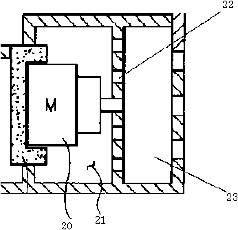
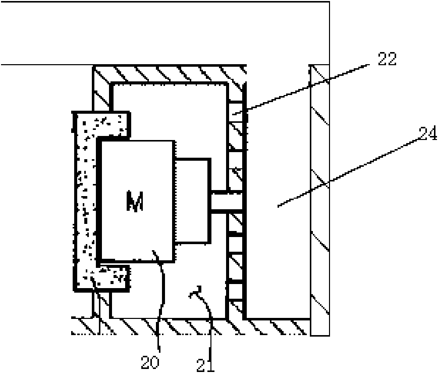
[0038] Figure 4 It is an exploded schematic view of the motor cover of the vacuum cleaner of the present invention; Figure 5 It is a sectional view of the motor cover of the vacuum cleaner of the present invention; Image 6 It is a structural schematic diagram of the sleeve in the motor cover of the vacuum cleaner of the present invention; Figure 7 It is a cross-sectional view of the sleeve in the motor cover of the vacuum cleaner of the present invention.

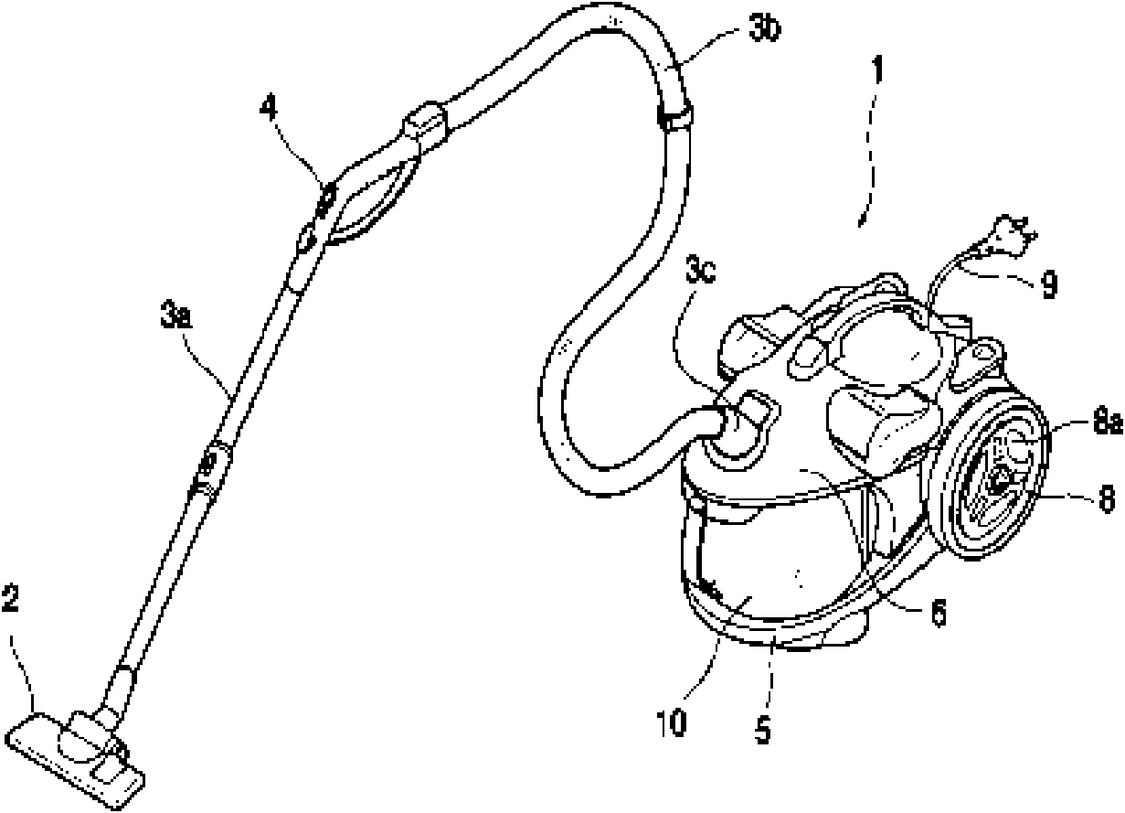
[0039] like Figure 4 to Figure 7As shown, the motor cover of the vacuum cleaner of the present invention is arranged inside the body of the vacuum cleaner, the motor 20 of the vacuum cleaner is fixed, and the flow direction of the air discharged from the motor is guided, wherein the casing 30 and the casing cover 31 provided with an air inlet form the appearance of the motor cover , surround the motor ...


PUM


Abstract

The invention discloses a motor cover for a dust collector. The motor cover is arranged inside a body of the dust collector, is fixed with a motor of the dust collector and guides the flowing direction of air exhausted by the motor. The motor cover comprises a shell and an exhaust outlet, wherein the shell is combined with a shell cover to form the motor cover, surrounds the motor and forms an enclosed exhaust space around the motor; the exhaust outlet is formed on the shell and is communicated with spaces inside and outside the motor cover to directionally exhaust the air inside the exhaust space; a sleeve is arranged inside the shell around the motor and comprises an externally sealed back plate and a noise-reducing plate arranged on the inner side of the back plate; a space is respectively reserved among the noise-reducing plate, the motor and the back plate, and the noise-reducing plate and the back plate form a whole; a plurality of through holes are formed on the noise-reducing plate; and exhaust holes are formed on the sleeve. By changing the thickness of the noise-reducing plate, diameters of the through holes formed on the noise-reducing plate, porosity and other parameters, a specific part in noise is pertinently weakened and eliminated; therefore, the sound quality of the noise is changed.

Description

technical field [0001] The invention belongs to the technical field of vacuum cleaners, and specifically relates to a sealed shell with a noise reduction plate inside corresponding to the exhaust part of the motor, so that the noise characteristics can be changed when the air discharged from the motor flows through the noise reduction plate, thereby changing the noise quality of the vacuum cleaner The motor cover of the vacuum cleaner. technical background [0002] Vacuum cleaner is a kind of household appliance for indoor cleaning and sanitation, which is used to remove dust from floors, carpets, walls, furniture, clothing and various gaps. Generally speaking, a vacuum cleaner mainly includes a suction device and a suction pipeline. The suction device mainly formed by a motor and a fan is arranged in the body. The suction pipeline includes a suction head and a suction pipe. The air port communicates with the air inlet of the fan inside the body through the telescopic pipe ...

Claims


Application Information

Patent Timeline
Patent Type & Authority Applications(China)
IPC IPC(8): H02K5/24A47L9/28
Inventor 穆道津魏君泰郑康
Owner LG ELECTRONICS (TIANJIN) APPLIANCES CO LTD
Why Eureka
Try Eureka